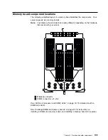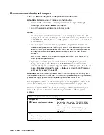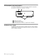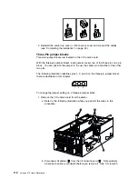
I/O function card component locations
The following simplified layout of the I/O function card identifies the components.
1
External SCSI connector (channel A)
2
CD-ROM drive connector
3
SCSI B detect jumper (J19)
4
Internal SCSI connector (channel B)
5
Diskette drive connector
6
Front panel connector
7
Advanced System Management PCI adapter connector
8
Battery
9
Flash page swap jumper (J13)
1
Power-on password override jumper (J14)
11
Clear CMOS register contents jumper (J15)
12
Video port connector (note 1)
13
Parallel port connector
14
Serial port A connector
15
Serial port B connector
16
Keyboard connector (note 2)
17
Mouse connector
Notes:
1. The video port connector is a 15-pin, D-shell connector behind the parallel port
connector.
2. The keyboard connector is behind the mouse connector, and is closer to the
circuit side of the board.
Attention
You cannot clear the administrator password by changing the CMOS jumper. If
an administrator password is set and then forgotten, contact your IBM service
technician.
Chapter 5. Board and adapter components
103
Summary of Contents for eServer 370 xSeries
Page 1: ...User s Reference xSeries 370...
Page 2: ......
Page 3: ...IBM xSeries 370 User s Reference...
Page 32: ...16 xSeries 370 User s Reference...
Page 188: ...172 xSeries 370 User s Reference...


