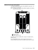
Memory board component locations
The following simplified layout of a memory board identifies the components. Your
server supports two memory boards.
Note:
Your memory board might look slightly different, depending on the hardware
that comes with your server.
16
1
1
Midplane connector
2
DIMM connectors (J1–J16)
See “LED card (processor and DIMM) LEDs” on page 157 for details about the
DIMM error LEDs.
See “Installing DIMMs and memory boards” on page 52 for instructions on
installing a DIMM on a memory board, and installing a memory board in the server.
Chapter 5. Board and adapter components
105
Summary of Contents for eServer 370 xSeries
Page 1: ...User s Reference xSeries 370...
Page 2: ......
Page 3: ...IBM xSeries 370 User s Reference...
Page 32: ...16 xSeries 370 User s Reference...
Page 188: ...172 xSeries 370 User s Reference...


