


Notes:
1. The 100 MHz DIMMs support the registered mode of operation.
2. Install DIMMs with a maximum height of 4.32 cm (1.7 inches).
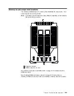
3. Your server comes with one standard memory board (A), and one or more
DIMMs installed on this memory board. You can install an optional memory
board (B). Both the standard memory board (A) and the optional memory
board (B) contain 16 DIMM connectors (J1–J16).
4. When you install DIMMs in both the standard memory board (A) and the
optional memory board (B), you must install them in matching pairs with the
same part number, in the same slot on each memory board; for example,
J1/J1, J5/J5, J9/J9, and so on.
5. The connector identifiers located on both the standard (A) and the optional (B)
memory boards are J1–J16. To distinguish the two memory boards, use the
labels provided on the processor housing assembly. These labels refer to the
connector identifiers as A1–A16 on the standard memory board, and B1–B16
on the optional memory board.
6. Your server comes with a system label on the server cover. The numbers
located to the right of the memory boards on the system label do not indicate
DIMM connector identifiers. These numbers indicate the DIMMs; for example,
1
means the first DIMM that you install,
9
means the ninth DIMM that you
install, and so on.
106
xSeries 370 User's Reference
Summary of Contents for eServer 370 xSeries
Page 1: ...User s Reference xSeries 370...
Page 2: ......
Page 3: ...IBM xSeries 370 User s Reference...
Page 32: ...16 xSeries 370 User s Reference...
Page 188: ...172 xSeries 370 User s Reference...


