


card component locations” on page 103 for the connector locations on the
I/O function card.
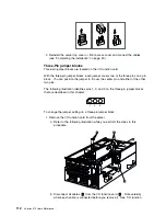
c. Remove the two screws
4
located on the metal connector plate inside the
server.
d. Remove the I/O function card retention bracket
3
on the right side of the
card by pulling out the fastener on the bracket.
e. Carefully grasp the I/O function card by its top edge and pull the I/O
function card out of the server.
f. Place the I/O function card connector-side up on a flat, static-protective
surface.
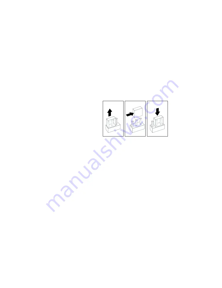
2. Lift the jumper straight off the pin block.
3. Align the holes in the bottom of the jumper with the center pin and the pin that
was not covered previously.
4. Slide the jumper fully onto these pins.
Chapter 5. Board and adapter components
113
Summary of Contents for eServer 370 xSeries
Page 1: ...User s Reference xSeries 370...
Page 2: ......
Page 3: ...IBM xSeries 370 User s Reference...
Page 32: ...16 xSeries 370 User s Reference...
Page 188: ...172 xSeries 370 User s Reference...


