


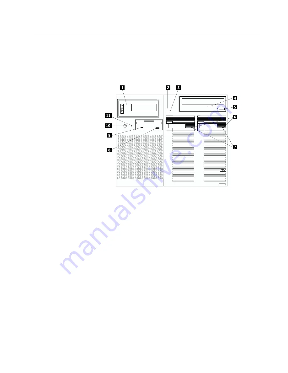
Controls and indicators
The most commonly used controls and status indicators are on the front of your
server.
1
Front panel:
The lights and messages on this panel give status information
for your server. See “Front panel” on page 43 for more information.
2
Scroll button:
Press this button to select an action to perform on a
system-monitoring message; then, press the Enter button to perform the
action. You can select:
Keep
to retain the message on the front panel and enable the system
error light to continue to flash
Remind
to retain the message on the front panel and enable the system
error light to flash slowly
Clear
to clear the message from the front panel and enable the system
error light to stop flashing
3
Enter button:
Press this button to perform an action on system-monitoring
messages that appear on the front panel.
4
CD-ROM drive in-use light:
When this light is on, the CD-ROM drive is
being accessed.
5
CD-ROM eject/load button:
Press this button to eject or retract the
CD-ROM tray so that you can insert or remove a CD.
6
Hard disk drive status light:
This light operates only in a ServeRAID
environment. Each of the hot-swap drives has a Hard Disk Drive Status light.
When the amber light for a hard disk drive is on continuously, the drive has
failed. When the light flashes slowly (one flash per second), the drive is being
rebuilt. When the light flashes rapidly (three flashes per second), the
ServeRAID controller is identifying the drive.
Chapter 3. Server power, controls, and indicators
41
Summary of Contents for eServer 370 xSeries
Page 3: ...IBM xSeries 370 Installation Guide...
Page 6: ...iv xSeries 370 Installation Guide...
Page 20: ...8 xSeries 370 Installation Guide...
Page 50: ...38 xSeries 370 Installation Guide...
Page 56: ...44 xSeries 370 Installation Guide...
Page 68: ...56 xSeries 370 Installation Guide...
Page 84: ...72 xSeries 370 Installation Guide...
Page 91: ......


