


Electronic
Emission
Notices
Federal
Communications
Commission
(FCC)
statement
Note:
This
equipment
has
been
tested
and
found
to
comply
with
the
limits
for
a
Class
A
digital
device,
pursuant
to
Part
15
of
the
FCC
Rules.
These
limits
are
designed
to
provide
reasonable
protection
against
harmful
interference
when
the
equipment
is
operated
in
a
commercial
environment.
This
equipment
generates,
uses,
and
can
radiate
radio
frequency
energy
and,
if
not
installed
and
used
in
accordance
with
the
instruction
manual,
may
cause
harmful
interference
to
radio
communications.
Operation
of
this
equipment
in
a
residential
area
is
likely
to
cause
harmful
interference,
in
which
case
the
user
will
be
required
to
correct
the
interference
at
his
own
expense.
Properly
shielded
and
grounded
cables
and
connectors
must
be
used
in
order
to
meet
FCC
emission
limits.
IBM
is
not
responsible
for
any
radio
or
television
interference
caused
by
using
other
than
recommended
cables
and
connectors
or
by
unauthorized
changes
or
modifications
to
this
equipment.
Unauthorized
changes
or
modifications
could
void
the
user’s
authority
to
operate
the
equipment.
This
device
complies
with
Part
15
of
the
FCC
rules.
Operation
is
subject
to
the
following
two
conditions:
(1)
this
device
may
not
cause
harmful
interference,
and
(2)
this
device
must
accept
any
interference
received,
including
interference
that
may
cause
undesired
operation.
Responsible
Party:
International
Business
Machines
Corporation
New
Orchard
Road
Armonk,
NY
10504
Telephone:
1-919-543-2193
Industry
Canada
Compliance
Statement
This
Class
A
digital
apparatus
meets
the
requirements
of
the
Canadian
Interference-Causing
Equipment
Regulations.
Avis
de
conformité
à
la
réglementation
d’Industrie
Canada
Cet
appareil
numérique
de
la
classe
A
respecte
toutes
les
exigences
du
Règlement
sur
le
matériel
brouilleur
du
Canada.
European
Community
Compliance
Statement
This
product
is
in
conformity
with
the
protection
requirements
of
EU
Council
Directive
89/336/EEC
on
the
approximation
of
the
laws
of
the
Member
States
relating
to
electromagnetic
compatibility.
IBM
cannot
accept
responsibility
for
any
failure
to
satisfy
the
protection
requirements
resulting
from
a
non-recommended
modification
of
the
product,
including
the
fitting
of
non-IBM
option
cards.
Australia
and
New
Zealand
Class
A
statement
Attention:
This
is
a
Class
A
product.
In
a
domestic
environment
this
product
may
cause
radio
interference
in
which
case
the
user
may
be
required
to
take
adequate
measures.
VCCI
Statement
-
Japan
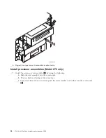
38
270,
800,
810
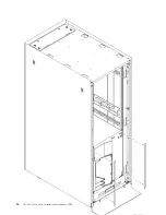
In
Rack
Installation
Instructions
V5R3
Summary of Contents for Eserver i Series
Page 1: ...iSeries 270 800 and 810 units in a rack installation instructions Version 5 ERserver...
Page 2: ......
Page 3: ...iSeries 270 800 and 810 units in a rack installation instructions Version 5 ERserver...
Page 6: ...iv 270 800 810 In Rack Installation Instructions V5R3...
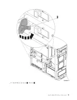
Page 11: ...__ 8 Open the back door Install a Model 270 800 or 810 in a rack 5...
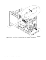
Page 16: ...A Guidepins B Clips 10 270 800 810 In Rack Installation Instructions V5R3...
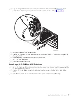
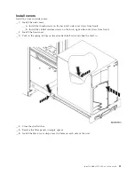
Page 35: ...__ 2 Install the access cover A Push in B Install a Model 270 800 or 810 in a rack 29...
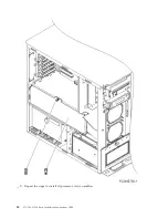
Page 38: ...32 270 800 810 In Rack Installation Instructions V5R3...
Page 40: ...34 270 800 810 In Rack Installation Instructions V5R3...
Page 48: ...42 270 800 810 In Rack Installation Instructions V5R3...
Page 49: ......
Page 50: ...Printed in USA...


