background image

The


following


is


a


summary


of


the


VCCI


Japanese


statement


in


the


box


above.


This


is


a


Class


A


product


based


on


the


standard


of


the


Voluntary


Control


Council


for


Interference


by


Information


Technology


Equipment


(VCCI).


If


this


equipment


is


used


in


a


domestic


environment,


radio


disturbance


may


arise.


When


such


trouble


occurs,


the


user


may


be


required


to


take


corrective


actions.


Electromagnetic


Interference


(EMI)


Statement


-


People’s


Republic


of


China


Per


GB


9254–1998,


the


user


manual


for


a


Class


A


product


must


carry


the


following


warning


message


(English


translation


from


the


Chinese


standard)


about


use


in


a


residential


environment


in


Chinese


(

Simplified


Chinese

):


Declaration:


This


is


a


Class


A


product.


In


a


domestic


environment


this


product


may


cause


radio


interference


in


which


case


the


user


may


need


to


perform


practical


action.


Electromagnetic


Interference


(EMI)


Statement


-


Taiwan


The


following


is


a


summary


of


the


EMI


Taiwan


statement


above.


Warning:


This


is


a


Class


A


product.


In


a


domestic


environment


this


product


may


cause


radio


interference


in


which


case


the


user


will


be


required


to


take


adequate


measures.


Radio


Protection


for


Germany


Dieses


Gerät


ist


berechtigt


in


Übereinstimmung


mit


Dem


deutschen


EMVG


vom


9.Nov.92


das


EG–Konformitätszeichen


zu


führen.


Der


Aussteller


der


Konformitätserklärung


ist


die


IBM


Germany.


Dieses


Gerät


erfüllt


die


Bedingungen


der


EN


55022


Klasse


A.


Für


diese


von


Geräten


gilt


folgende


Bestimmung


nach


dem


EMVG:


Appendix.


Notices


39

Summary of Contents for Eserver i Series

Page 1: ...iSeries 270 800 and 810 units in a rack installation instructions Version 5 ERserver...

Page 2: ......

Page 3: ...iSeries 270 800 and 810 units in a rack installation instructions Version 5 ERserver...

Page 4: ...product number 5722 SS1 and to all subsequent releases and modifications until otherwise indicated in new editions This version does not run on all reduced instruction set computer RISC models nor do...

Page 5: ...assemblies Model 270 only 20 Install unit in the rack 22 Install devices that were removed 25 Electrostatic discharge 25 Install disk units 26 Install tape CD ROM and DVD devices 27 Install processor...

Page 6: ...iv 270 800 810 In Rack Installation Instructions V5R3...

Page 7: ...uneven mechanical loading when installing a unit in a rack If the rack has a stabilizer it must be firmly attached before uninstalling or removing this unit v Consideration should be given to the con...

Page 8: ...IBM Rochester Manufacturing Automated Information Line R MAIL at 1 800 300 8751 v In countries outside of the United States Use the following Web site to locate your service and support numbers http w...

Page 9: ...Unplug any power cords such as printers and displays from electrical outlets __ 8 Unplug the system unit and expansion unit power cords from the electrical outlets Rack installation instructions __ 1...

Page 10: ...__ 7 Remove all the filler panels to allow access to the inside of the rack enclosure 4 270 800 810 In Rack Installation Instructions V5R3...

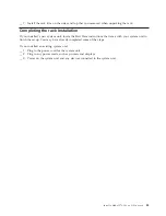
Page 11: ...__ 8 Open the back door Install a Model 270 800 or 810 in a rack 5...

Page 12: ...__ 9 Plan where you will place the units you are installing in the rack Place the larger and heavier units in the lower part of the rack 6 270 800 810 In Rack Installation Instructions V5R3...

Page 13: ...with rail assembly B adapter plate C clips and screws D Some extra screws are provided __ 2 Install the adapter plate on the shelf __ a Locate the 10 screws to install the 270 800 or 810 shelf plate _...

Page 14: ..._ 3 Install four clips on the front of the rack If you are installing the unit in the lower part of the rack place the clips in EIA sections 1 and 2 8 270 800 810 In Rack Installation Instructions V5R...

Page 15: ...To install in the upper part place the clips in EIA sections 17 and 18 Install a Model 270 800 or 810 in a rack 9...

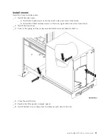
Page 16: ...A Guidepins B Clips 10 270 800 810 In Rack Installation Instructions V5R3...

Page 17: ...e other one in the front of the rack __ 5 Lift the shelf and rail assembly into the rack from the front You need to slant the shelf to fit through the front opening __ 6 Align and insert the guidepins...

Page 18: ...8 Install two screws on each side of the back frame to secure the shelf assembly __ 9 Open the latches on the shelf A Slide the shelf partially out Install the two screws on each side of the front fr...

Page 19: ...ll in the correct position __ 10 Slide the shelf into the rack __ 11 Press in the latches to lock the shelf in the rack __ 12 Locate the cable management arm assembly __ 13 Push in the latches to secu...

Page 20: ...s before lifting the system unit into the rack To safely lift your unit onto the rack shelf use the instructions to remove devices from the unit Place devices that you remove in the electrostatic disc...

Page 21: ...liner from the copper foil at the end when you unroll the strap 3 Attach the copper foil to an exposed unpainted metal surface on the frame of the system unit electrical ground 4 Place devices that y...

Page 22: ...2 Remove the disk unit covers Squeeze the latch and pull out __ 3 It is very important to label the disk units and locations as you remove them so they are later installed in the exact same position F...

Page 23: ...emove the disk unit If the handle is not all the way down the disk unit will not slide out of the system __ 5 Support the bottom of the disk unit assembly as you slide it completely out Do not hold th...

Page 24: ...ns Remove tape CD ROM or DVD devices __ 1 Disconnect the signal larger connector and power smaller connector cables from the back of the device Access to these connectors is from the side of the syste...

Page 25: ...e device by sliding it forward and out of the system unit You may need to remove the filler blank above the control panel __ 4 Place the device in a static protective bag Install a Model 270 800 or 81...

Page 26: ...1 Remove the access cover A Pull out latch B __ 2 Remove the processor card assemblies A and B by doing the following __ a Unlatch the two latches C until the card assembly slightly pops out 20 270 8...

Page 27: ...at the same time to remove the card assembly from the system unit __ c Put the card assembly in a static protective bag __ 3 Repeat the steps to remove all processor card assemblies Install a Model 27...

Page 28: ...hat a rack stabilizer is attached to the bottom front of the rack Do not pull out more than one unit at a time The rack can turn over if you pull out more than one unit at a time RSFTC224 __ 2 Install...

Page 29: ...hed to the shelf the six holes where you will install screws to securely attach the unit to the shelf __ 6 Lift the unit onto the shelf positioning it toward the back of the shelf __ 7 Slide the syste...

Page 30: ...__ 8 Install the six screws from the bottom of the rack shelf to secure the unit to the shelf 24 270 800 810 In Rack Installation Instructions V5R3...

Page 31: ...the following instructions to install the devices that were removed Electrostatic discharge Attach the disposable wrist strap to prevent electrostatic discharge from damaging a device View video Attac...

Page 32: ...rom the copper foil at the end when you unroll the strap 3 Attach the copper foil to an exposed unpainted metal surface on the frame of the unit electrical ground Install disk units __ 1 The disk unit...

Page 33: ...atch __ 6 Repeat the above steps for each disk unit in your system __ 7 Install the disk unit covers __ 8 Continue with the instructions Install tape CD ROM and DVD devices __ 1 Install the device by...

Page 34: ...tall the processor card assembly A by doing the following __ a Slide the card assembly into the system unit __ b Push on both card latches at the same time __ c Close the latches when you cannot push...

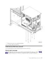
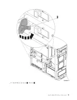
Page 35: ...__ 2 Install the access cover A Push in B Install a Model 270 800 or 810 in a rack 29...

Page 36: ...__ 3 Repeat the steps to install all processor card assemblies 30 270 800 810 In Rack Installation Instructions V5R3...

Page 37: ...ted retainer screws on the back right side cover view from front __ 2 Install the front cover __ 3 Push in the spring latches on the extended shelf rails and slide the shelf in __ 4 Close the shelf la...

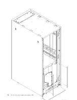
Page 38: ...32 270 800 810 In Rack Installation Instructions V5R3...

Page 39: ...nstructions that came with your system unit to finish the set up You may have already completed some of the steps If you installed an existing system unit __ 1 Plug in the power cord for the system un...

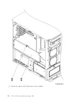
Page 40: ...34 270 800 810 In Rack Installation Instructions V5R3...

Page 41: ...ot apply to you This information could include technical inaccuracies or typographical errors Changes are periodically made to the information herein these changes will be incorporated in new editions...

Page 42: ...cific machines indicated IBM makes no representations that it is suitable for any other purpose The drawings and specifications contained herein shall not be reproduced in whole or in part without the...

Page 43: ...contained therein IBM reserves the right to withdraw the permissions granted herein whenever in its discretion the use of the Publications is detrimental to its interest or as determined by IBM the a...

Page 44: ...ration is subject to the following two conditions 1 this device may not cause harmful interference and 2 this device must accept any interference received including interference that may cause undesir...

Page 45: ...n Chinese Simplified Chinese Declaration This is a Class A product In a domestic environment this product may cause radio interference in which case the user may need to perform practical action Elect...

Page 46: ...ion reception which can be determined by turning the equipment off and on the user is encouraged to try to correct the interference by one or more of the following measures v Reorient or relocate the...

Page 47: ...tion cards This product has been tested and found to comply with the limits for Class B Information Technology Equipment according to CISPR 22 European Standard EN 55022 The limits for Class B equipme...

Page 48: ...42 270 800 810 In Rack Installation Instructions V5R3...

Page 49: ......

Page 50: ...Printed in USA...

Reviews: