

Electrostatic
discharge
Attach
the
disposable
wrist
strap
to
prevent
electrostatic
discharge
from
damaging
a
device.
Attach
the
adhesive
part
of
the
foil
to
an
unpainted
surface
on
the
frame
of
the
unit.
Notes:
1.
Follow
the
same
precautions
you
would
use
without
the
wrist
strap.
The
2209
Disposable
Wrist
Strap
is
for
static
control.
It
will
not
increase
or
decrease
your
risk
of
receiving
electric
shock
when
using
or
working
on
electrical
equipment.
2.
Remove
the
liner
from
the
copper
foil
at
the
end
when
you
unroll
the
strap.
3.
Attach
the
copper
foil
to
an
exposed,
unpainted
metal
surface
on
the
frame
of
the
system
unit
(electrical
ground).
4.
Place
devices
that
you
remove
in
electrostatic
discharge
bags
to
prevent
damage.
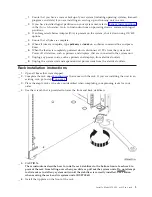
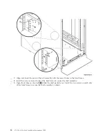
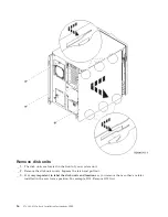
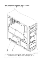
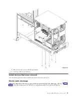
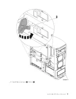
Remove
covers
Remove
the
front
and
side
covers.
__
1.
Remove
the
front
cover
by
gripping
the
sides
of
the
cover
and
pulling
the
cover
toward
you.
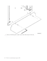
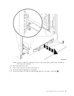
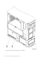
__
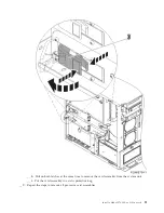
2.
Remove
the
side
covers
by
loosening
and
removing
the
two
thumbscrews
and
the
two
slotted
retainer
screws
on
the
back
of
the
system
unit.
Slide
each
of
the
covers
from
front
to
back
until
it
stops.
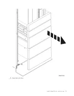
__
3.
Pull
the
cover
out.
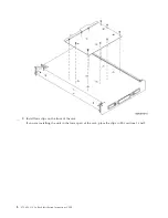
Install
a
Model
270,
800,
or
810
in
a
rack
15
Summary of Contents for Eserver i Series
Page 1: ...iSeries 270 800 and 810 units in a rack installation instructions Version 5 ERserver...
Page 2: ......
Page 3: ...iSeries 270 800 and 810 units in a rack installation instructions Version 5 ERserver...
Page 6: ...iv 270 800 810 In Rack Installation Instructions V5R3...
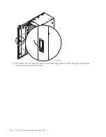
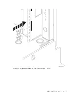
Page 11: ...__ 8 Open the back door Install a Model 270 800 or 810 in a rack 5...
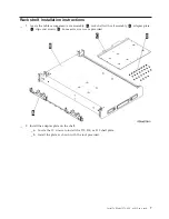
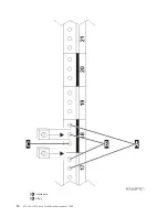
Page 16: ...A Guidepins B Clips 10 270 800 810 In Rack Installation Instructions V5R3...
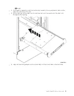
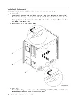
Page 35: ...__ 2 Install the access cover A Push in B Install a Model 270 800 or 810 in a rack 29...
Page 38: ...32 270 800 810 In Rack Installation Instructions V5R3...
Page 40: ...34 270 800 810 In Rack Installation Instructions V5R3...
Page 48: ...42 270 800 810 In Rack Installation Instructions V5R3...
Page 49: ......
Page 50: ...Printed in USA...