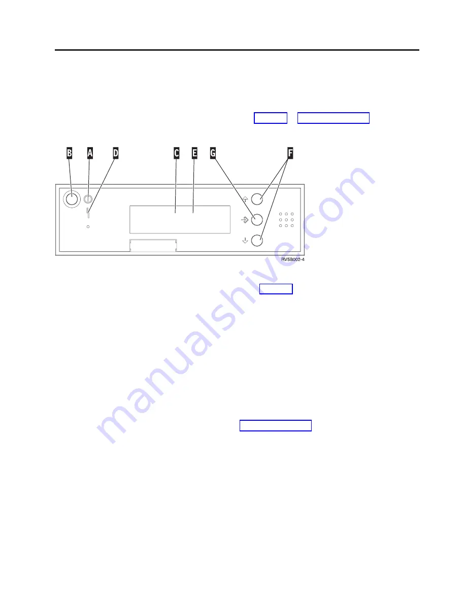
System-unit control panel
Go to the front of your iSeries system unit. Open the control panel door.
Your control panel looks like either Figure 22 or Figure 23 on page 34. Refer to the
control panel for your unit.
Following are the descriptions of the Figure 22 callouts:
A
Power On Light
v
A blinking light indicates power to the unit.
v
A constant light indicates that the unit is on and working.
B
Power Push button
C
Processor Activity
D
System Attention
E
Function/Data Display
F
Increment/Decrement buttons
G
Enter Push button
If your control panel looks like Figure 23 on page 34, before you can use
F
Increment/Decrement buttons and
G
Enter push button, you need to press
H
Mode Selects to select Manual mode
N
. To use Mode Select, the keystick needs to
be inserted.
Figure 22. Control panel without Electronic Keystick
© Copyright IBM Corp. 2000, 2003
33
Summary of Contents for eserver iSeries 270
Page 1: ...iSeries 270 810 820 825 30xx Memory Installation Version 5 ERserver ...
Page 2: ......
Page 3: ...iSeries 270 810 820 825 30xx Memory Installation Version 5 ERserver ...
Page 23: ...Figure 17 Memory Connectors View 1 Install memory 19 ...
Page 34: ...30 30xx Memory Card Installation V5R2 ...
Page 36: ...__ 3 Pull the cover out 32 30xx Memory Card Installation V5R2 ...
Page 39: ......
Page 40: ... Printed in U S A ...


