background image

C09


HSL


C08


HSL


Imbed


IOA


C06


C05


C04


C03


C02


C01


__


6.


Open


the


latch


at


the


card


position


where


you


plan


to


remove


the


card.


Move


the


latch


counterclockwise


and


then


swing


the


latch


out.


26


Model


825


In


Rack


Installation


Instructions


V5R3

Summary of Contents for eServer iSeries 825

Page 1: ...iSeries Model 825 in a rack installation instructions Version 5 ERserver...

Page 2: ......

Page 3: ...iSeries Model 825 in a rack installation instructions Version 5 ERserver...

Page 4: ...product number 5722 SS1 and to all subsequent releases and modifications until otherwise indicated in new editions This version does not run on all reduced instruction set computer RISC models nor do...

Page 5: ...emove PCI cards 25 Install unit in the rack 28 Install devices that were removed 32 Electrostatic discharge 32 Install disk units 33 Install fans 34 Install tape CD ROM and DVD devices 35 Install netw...

Page 6: ...iv Model 825 In Rack Installation Instructions V5R3...

Page 7: ...ted due to uneven mechanical loading when installing a unit in a rack If the rack has a stabilizer it must be firmly attached before uninstalling or removing this unit v Consideration should be given...

Page 8: ...ited States IBM Rochester Manufacturing Automated Information Line R MAIL at 1 800 300 8751 v In countries outside of the United States Use the following Web site to locate your service and support nu...

Page 9: ...it __ Unplug any power cords such as printers and displays from electrical outlets __ Unplug the system unit and expansion unit power cords from the electrical outlets Rack installation instructions _...

Page 10: ...__ 7 Remove all the filler panels to allow access to the inside of the rack enclosure 4 Model 825 In Rack Installation Instructions V5R3...

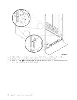
Page 11: ...__ 8 Open the back door Install a Model 825 in a rack 5...

Page 12: ...re you will place the units you are installing in the rack Install units in the lower part first Place the larger and heavier units in the lower part of the rack 6 Model 825 In Rack Installation Instr...

Page 13: ...rack shelf with rail assembly B adapter plate C clips and screws D Some extra screws are provided __ 2 Install the adapter plate on the shelf __ Locate the 10 screws to install the 825 adapter plate...

Page 14: ...Install four clips on the front of the rack If you are installing the system unit in the lower part of the rack place the clips in EIA sections 1 and 2 8 Model 825 In Rack Installation Instructions V...

Page 15: ...To install in the upper part place the clips in EIA sections 17 and 18 Install a Model 825 in a rack 9...

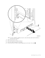
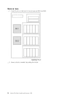
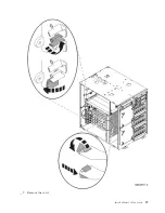
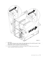
Page 16: ...A Guidepins B Clips 10 Model 825 In Rack Installation Instructions V5R3...

Page 17: ...and the other one in the front of the rack __ 5 Lift the shelf and rail assembly into the rack from the front You need to slant the shelf to fit through the front opening __ 6 Align and insert the gui...

Page 18: ...frame __ 8 Install two screws on each side of the back frame to secure the shelf assembly __ 9 Open the latches A on the shelf Slide the shelf partially out Install the two screws on each side of the...

Page 19: ...are still in the correct position __ 10 Slide the shelf into the rack __ 11 Press in the latches to lock shelf in the rack __ 12 Locate the cable management arm assembly __ 13 Push in the latches to...

Page 20: ...re lifting the system unit into the rack To safely lift your system unit onto the rack shelf follow the instructions to remove devices from the unit Place devices that you remove in the electrostatic...

Page 21: ...ripping the sides of the cover and pulling the cover toward you A __ 2 Remove the side covers by loosening and removing the two thumbscrews and the two slotted retainer screws on the back Slide each o...

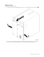
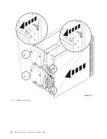
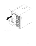
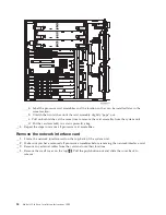
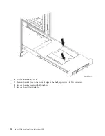
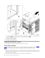
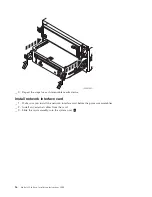
Page 22: ...__ 3 Pull the cover out 16 Model 825 In Rack Installation Instructions V5R3...

Page 23: ...supply area at the back of the unit P01 and P02 __ 2 Pull the latch on the power supply handle __ 3 Lift up the handle on the power supply __ 4 Support the bottom of the supply as you slide it out of...

Page 24: ...receiving electric shock when using or working on electrical equipment 2 Remove the liner from the copper foil at the end when you unroll the strap 3 Attach the copper foil to an exposed unpainted met...

Page 25: ...sk unit will not slide out of the system __ 4 Support the bottom of the disk unit assembly as you slide it completely out of the system Do not hold the disk unit by the handle __ 5 Label the disk unit...

Page 26: ...Remove fans __ 1 Locate the fans in the front of your system unit B01 and B02 __ 2 Remove the fan assembly by pulling the latches 20 Model 825 In Rack Installation Instructions V5R3...

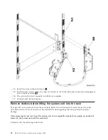
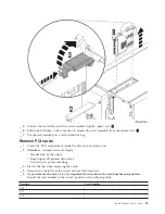
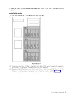
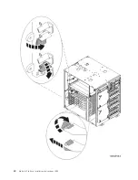
Page 27: ...__ 3 Repeat for each fan Install a Model 825 in a rack 21...

Page 28: ...the front of the system unit __ 2 Pull both handles on both sides of the device toward you __ 3 Slide the device out __ 4 Do not hold the device by the handles __ 5 Place the device in a static prote...

Page 29: ...ch device Remove processor assembly __ 1 Locate the processor assembly inside the side of the system unit __ 2 Remove the access cover A __ 3 Remove the processor card assemblies by doing the followin...

Page 30: ...c protective bag __ 4 Repeat the steps to remove all processor card assemblies Remove the network interface card __ 1 Locate the network interface card on the top back of the system unit __ 2 Make sur...

Page 31: ...our system unit __ 2 Attention Adapter cards are fragile v Handle only by the edges v Keep fingers off printed circuit area v Use static strap when handling __ 3 Start at the top when removing the car...

Page 32: ...ed IOA C06 C05 C04 C03 C02 C01 __ 6 Open the latch at the card position where you plan to remove the card Move the latch counterclockwise and then swing the latch out 26 Model 825 In Rack Installation...

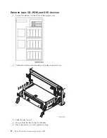
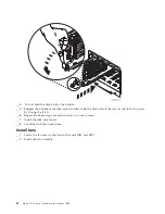
Page 33: ...__ 7 Remove the card Install a Model 825 in a rack 27...

Page 34: ...that is not steady Before you pull the unit out of the rack ensure that a rack stabilizer is attached to the bottom front of the rack Do not pull out more than one unit at a time The rack can turn ov...

Page 35: ...three persons to safely lift this part or unit RSFTC205 __ 4 Pull the rack shelf out until fully extended and locked in place __ 5 Locate on the adapter plate that is attached to the shelf the two hol...

Page 36: ...elf __ 7 Position the unit close to the front of edge of the shelf approximately 2 5 centimeters __ 8 Remove the side covers with lifting bars __ 9 Remove the air flow deflector 30 Model 825 In Rack I...

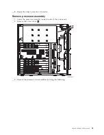
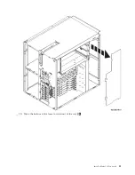
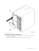
Page 37: ...__ 10 Move the bottom of the foam forward out of the way A Install a Model 825 in a rack 31...

Page 38: ...Electrostatic discharge Attach the disposable wrist strap to prevent electrostatic discharge from damaging a device View video Attach the adhesive part of the foil to an unpainted surface on the frame...

Page 39: ...unit __ 2 Locate the disk drives and look at the label of the disk unit It is very important to replace the disk units in the same exact location where they were removed __ 3 Squeeze and pull the hand...

Page 40: ...and lock it in place by closing the latch __ 6 Repeat the above steps for each disk unit in your system __ 7 Install the disk unit covers __ 8 Continue with the instructions Install fans __ 1 Locate t...

Page 41: ...s __ 1 Install the device by sliding it forward and into the system unit You may need to remove the filler blank above the control panel __ 2 Push the two latches that secure the device to the system...

Page 42: ...network interface card __ 1 Make sure you install the network interface card before the processor assemblies __ 2 Install any external cables from the card __ 3 Slide the card assembly into the syste...

Page 43: ...button Install processor assembly __ 1 Install the processor card assemblies by doing the following __ a Install the processor card assemblies in the correct location __ b Slide the card assembly into...

Page 44: ...__ 2 Install the access cover A __ 3 Repeat the steps to install all processor card assemblies 38 Model 825 In Rack Installation Instructions V5R3...

Page 45: ...install the card back into the same position it was removed Use the information you recorded earlier in step 5 on page 25 __ 3 Make sure the card latch is open at the card position where you plan to i...

Page 46: ...40 Model 825 In Rack Installation Instructions V5R3...

Page 47: ...at the bottom when installing the cards __ 6 Align the card with the card holders inside the system unit and push until it is connected securely __ 7 Swing the latch in and move the latch clockwise t...

Page 48: ...r screws on the back right side cover view from front Slide the shelf partially in to have space to tighten the screws with the tool provided __ 2 Install the front cover __ 3 Push in the spring latch...

Page 49: ...__ 4 Close the latches __ 5 Replace filler panels in empty spaces __ 6 Install the black cover strips over the holes on each side of the unit Install a Model 825 in a rack 43...

Page 50: ...44 Model 825 In Rack Installation Instructions V5R3...

Page 51: ...m unit __ 4 Move the handle down to lock in place __ 5 Push in the latch Completing the rack installation Locate the Start Here instructions that came with your unit to finish the set up of your unit...

Page 52: ...46 Model 825 In Rack Installation Instructions V5R3...

Page 53: ...ot apply to you This information could include technical inaccuracies or typographical errors Changes are periodically made to the information herein these changes will be incorporated in new editions...

Page 54: ...ecific machines indicated IBM makes no representations that it is suitable for any other purpose The drawings and specifications contained herein shall not be reproduced in whole or in part without th...

Page 55: ...contained therein IBM reserves the right to withdraw the permissions granted herein whenever in its discretion the use of the Publications is detrimental to its interest or as determined by IBM the a...

Page 56: ...eration is subject to the following two conditions 1 this device may not cause harmful interference and 2 this device must accept any interference received including interference that may cause undesi...

Page 57: ...n Chinese Simplified Chinese Declaration This is a Class A product In a domestic environment this product may cause radio interference in which case the user may need to perform practical action Elect...

Page 58: ...sion reception which can be determined by turning the equipment off and on the user is encouraged to try to correct the interference by one or more of the following measures v Reorient or relocate the...

Page 59: ...tion cards This product has been tested and found to comply with the limits for Class B Information Technology Equipment according to CISPR 22 European Standard EN 55022 The limits for Class B equipme...

Page 60: ...54 Model 825 In Rack Installation Instructions V5R3...

Page 61: ......

Page 62: ...Printed in USA...

Reviews: