


__
Ensure
that
you
have
a
current
backup
of
your
system
(including
operating
systems,
licensed
programs,
and
data)
if
you
are
installing
an
existing
up
and
running
unit
in
a
rack.
__
If
you
have
installed
logical
partitions
on
your
system
unit,
refer
to
the
iSeries
Information
Center
.
Go
to
in
the
iSeries
Information
Center
to
find
instructions
on
powering
down
a
system
with
logical
partitions.
__
If
an
Integrated
xSeries
Adapter
(IXA)
is
present
on
the
system,
shut
it
down
using
OS/400
options.
__
Ensure
that
all
jobs
are
complete.
__
When
all
jobs
are
complete,
type
pwrdwnsys
*immed
on
an
iSeries
command
line
and
press
Enter.
__
When
the
iSeries
is
completely
powered
down,
disconnect
all
PCs
from
the
system
unit.
Power
off
all
devices,
such
as
printers
and
displays,
that
are
connected
to
the
system
unit.
__
Unplug
any
power
cords,
such
as
printers
and
displays,
from
electrical
outlets.
__
Unplug
the
system
unit
and
expansion
unit
power
cords
from
the
electrical
outlets.
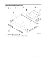
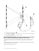
Rack
installation
instructions
__
1.
Open
all
boxes
that
were
shipped.
__
2.
Complete
the
rack
unpack
instructions
that
came
with
the
rack.
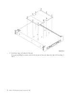
If
you
are
installing
the
unit
in
an
existing
rack,
go
to
step
__
3.
Place
the
empty
rack
at
the
site
you
identified
when
completing
your
planning
tasks
for
your
order.
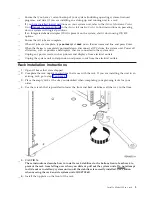
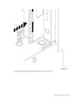
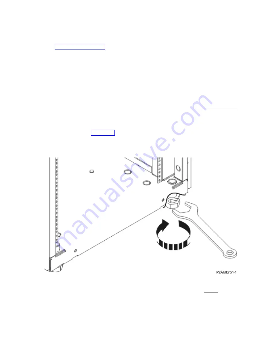
__
4.
Use
the
wrench
that
is
provided
to
lower
the
front
and
back
stabilizers
all
the
way
to
the
floor.
__
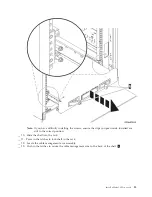
5.
CAUTION:
These
instructions
describe
how
to
install
a
rack
stabilizer
to
the
bottom
front
of
each
rack
to
prevent
the
rack
from
falling
over
when
you
slide
or
pull
out
the
system
units.
Do
not
attempt
to
slide
out
or
install
any
system
units
until
the
stabilizer
is
correctly
installed.
Use
caution
when
moving
the
rack
and
its
system
units.
(RSFTC063)
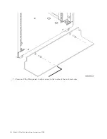
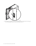
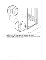
__
6.
Install
the
tip
plate
on
the
front
of
the
rack.
Install
a
Model
825
in
a
rack
3
Summary of Contents for eServer iSeries 825
Page 1: ...iSeries Model 825 in a rack installation instructions Version 5 ERserver...
Page 2: ......
Page 3: ...iSeries Model 825 in a rack installation instructions Version 5 ERserver...
Page 6: ...iv Model 825 In Rack Installation Instructions V5R3...
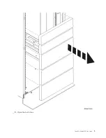
Page 11: ...__ 8 Open the back door Install a Model 825 in a rack 5...
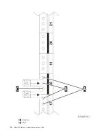
Page 16: ...A Guidepins B Clips 10 Model 825 In Rack Installation Instructions V5R3...
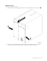
Page 22: ...__ 3 Pull the cover out 16 Model 825 In Rack Installation Instructions V5R3...
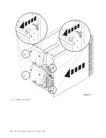
Page 27: ...__ 3 Repeat for each fan Install a Model 825 in a rack 21...
Page 33: ...__ 7 Remove the card Install a Model 825 in a rack 27...
Page 37: ...__ 10 Move the bottom of the foam forward out of the way A Install a Model 825 in a rack 31...
Page 46: ...40 Model 825 In Rack Installation Instructions V5R3...
Page 50: ...44 Model 825 In Rack Installation Instructions V5R3...
Page 52: ...46 Model 825 In Rack Installation Instructions V5R3...
Page 60: ...54 Model 825 In Rack Installation Instructions V5R3...
Page 61: ......
Page 62: ...Printed in USA...


