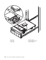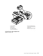
D10
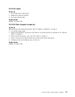
RIO
Cable
Removal
1.
Turn
off
the
power
to
the
system.
2.
Release
the
RIO
cable
retainers.
3.
Disconnect
the
RIO
cable.
Replacement
Replace
in
reverse
order.
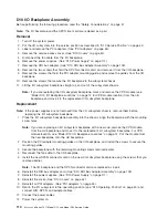
D10
RIO
Bus
Adapter
Assembly
Removal
Before
performing
the
following
procedure,
read
the
“Safety
Considerations”
on
page
41.
1.
Turn
off
the
system
power.
2.
Perform
the
procedure
to
put
the
I/O
subsystem
into
the
service
position
as
described
in
“D10
Service
Position”
on
page
43.
3.
Remove
the
service
access
cover.
(See
“D10
Covers”
on
page
44).
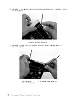
4.
Remove
the
screws
that
attach
the
RIO
riser
card
to
the
I/O
subsystem
chassis.
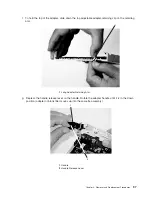
5.
Carefully
pull
the
card
straight
up
and
out
of
the
slot.
Replacement
Replace
in
reverse
order.
Chapter
3.
Removal
and
Replacement
Procedures
109
Summary of Contents for eserver pSeries 7311 D10
Page 1: ...pSeries 7311 Model D10 and Model D20 Service Guide SA38 0627 01 ERserver...
Page 2: ......
Page 3: ...pSeries 7311 Model D10 and Model D20 Service Guide SA38 0627 01 ERserver...
Page 8: ...vi Eserver pSeries 7311 Model D10 and Model D20 Service Guide...
Page 12: ...x Eserver pSeries 7311 Model D10 and Model D20 Service Guide...
Page 14: ...xii Eserver pSeries 7311 Model D10 and Model D20 Service Guide...
Page 25: ...1 Processor Subsystem 2 I O Subsystem Chapter 1 Reference Information 9...
Page 89: ...Chapter 3 Removal and Replacement Procedures 73...
Page 99: ...2 1 1 Top of Cassette 2 Handle Chapter 3 Removal and Replacement Procedures 83...
Page 179: ...D10 I O Subsystem Parts continued 1 2 3 4 5 6 7 Chapter 4 Parts Information 163...
Page 207: ......


