D20
Service
Access
Cover
Before
performing
the
following
procedure,
read
the
“Safety
Considerations”
on
page
41.
Opening
the
Service
Access
Cover
To
open
the
service
access
cover,
do
the
following:
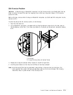
1.
Open
the
front
rack
door
and
place
the
Model
D20
subsystem
into
the
service
position
as
described
in
“D20
Service
Position”
on
page
113.
2.
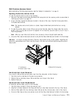
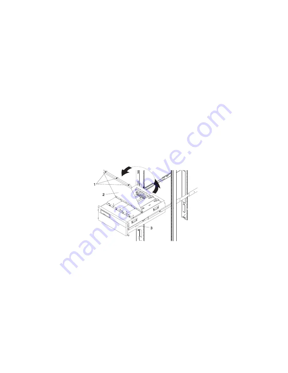
Loosen
the
three
captive
thumbscrews
located
on
the
rear
of
the
cover.
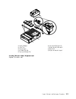
See
the
following
illustration
for
thumbscrew
locations.
Note:
The
service
access
cover
pivots
on
a
piano
hinge
located
directly
behind
the
four
cooling
blowers.
3.
To
open
the
service
access
cover,
lift
the
cover
up
from
the
back
edge.
The
hinges
allow
the
service
access
cover
to
swing
open
to
about
170
degrees.
Do
not
force
the
cover
to
come
to
a
rest
on
top
of
the
cooling
blowers.
Note:
When
you
open
the
service
access
cover,
ensure
you
have
enough
height
clearance.
4.
Close
and
then
secure
the
service
access
cover
with
the
three
thumbscrews
located
on
its
back
edge.
Attention:
For
proper
cooling
and
airflow,
close
the
cover
before
turning
on
the
system.
Operating
the
system
for
extended
periods
of
time
(over
30
minutes)
with
the
cover
opened
might
damage
the
system
components.
1
Thumbscrews
3
Model
D20
Subsystem
2
Service
Access
Cover
Service
Access
Cover
Removal
If
you
need
to
remove
the
service
access
cover
from
the
subsystem,
do
the
following:
1.
Open
the
cover
as
described
in
the
previous
procedure.
2.
Remove
the
four
retaining
screws
that
secure
the
cover
hinge
to
the
chassis.
3.
Remove
the
cover.
Service
Access
Cover
Replacement
To
install
the
service
access
cover,
do
the
following:
1.
Open
the
hinge,
located
on
the
service
access
cover.
2.
Align
the
four
holes
located
on
the
hinge
with
the
four
screw
holes
located
on
the
top
of
the
chassis.
3.
Start
and
then
tighten
the
four
retaining
screws
that
secure
the
service
access
cover
to
the
chassis.
4.
Close
and
then
secure
the
service
access
cover
with
the
three
thumbscrews
located
on
its
back
edge.
Chapter
3.
Removal
and
Replacement
Procedures
115
Summary of Contents for eserver pSeries 7311 D10
Page 1: ...pSeries 7311 Model D10 and Model D20 Service Guide SA38 0627 01 ERserver...
Page 2: ......
Page 3: ...pSeries 7311 Model D10 and Model D20 Service Guide SA38 0627 01 ERserver...
Page 8: ...vi Eserver pSeries 7311 Model D10 and Model D20 Service Guide...
Page 12: ...x Eserver pSeries 7311 Model D10 and Model D20 Service Guide...
Page 14: ...xii Eserver pSeries 7311 Model D10 and Model D20 Service Guide...
Page 25: ...1 Processor Subsystem 2 I O Subsystem Chapter 1 Reference Information 9...
Page 89: ...Chapter 3 Removal and Replacement Procedures 73...
Page 99: ...2 1 1 Top of Cassette 2 Handle Chapter 3 Removal and Replacement Procedures 83...
Page 179: ...D10 I O Subsystem Parts continued 1 2 3 4 5 6 7 Chapter 4 Parts Information 163...
Page 207: ......


