D20
Blowers
Before
performing
the
following
procedure,
read
“Safety
Considerations”
on
page
41.
Each
cooling
blower
assembly
has
a
green
LED
and
an
amber
LED.
The
green
LED
indicates
when
the
cooling
blower
is
receiving
power.
A
blinking
amber
LED
indicates
when
the
cooling
blower
needs
attention
from
a
potential
cooling
problem.
When
you
are
standing
in
front
of
and
facing
the
I/O
subsystem,
the
cooling
blowers
are
labeled
from
left
to
right,
1
through
4,
across
the
top
blower
retaining
bracket.
Attention:
If
the
I/O
subsystem
does
not
have
two
functional
power
supplies
installed,
do
not
remove
a
blower
with
the
power
turned
on.
If
only
one
power
supply
is
functional,
removing
of
a
blower
will
cause
the
system
to
turn
power
off.
Hot-Swap
Blower
Removal
To
remove
a
hot-swap
blower,
do
the
following:
1.
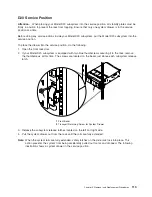
Put
the
Model
D20
subsystem
into
the
service
position
as
described
in
“D20
Service
Position”
on
page
113.
2.
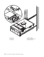
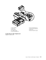
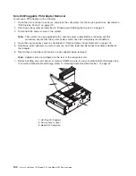
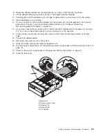
Locate
the
cooling
blower
assemblies,
as
shown
in
the
following
illustration.
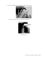
3.
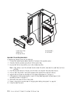
Pull
out
the
snap
button
located
on
the
front
flange
of
the
failing
blower.
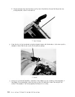
4.
Using
the
snap
button
as
a
handle,
pull
the
front
of
the
blower
up,
allowing
the
back
edge
to
pivot
on
a
recessed
ledge
located
just
below
the
back
edge
of
the
blower.
Note:
Using
the
snap
button,
lift
the
blower
from
the
chassis.
The
blower
connector
will
disconnect
from
its
docking
connector,
which
is
located
on
the
underside
of
the
blower.
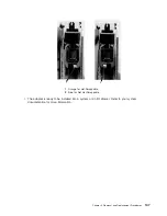
5.
Pull
the
blower
away
from
the
system.
Ensure
that
the
two
back
tabs,
located
on
the
bottom
back
edge
of
the
blower
assembly,
have
cleared
their
retaining
slots.
Chapter
3.
Removal
and
Replacement
Procedures
119
Summary of Contents for eserver pSeries 7311 D10
Page 1: ...pSeries 7311 Model D10 and Model D20 Service Guide SA38 0627 01 ERserver...
Page 2: ......
Page 3: ...pSeries 7311 Model D10 and Model D20 Service Guide SA38 0627 01 ERserver...
Page 8: ...vi Eserver pSeries 7311 Model D10 and Model D20 Service Guide...
Page 12: ...x Eserver pSeries 7311 Model D10 and Model D20 Service Guide...
Page 14: ...xii Eserver pSeries 7311 Model D10 and Model D20 Service Guide...
Page 25: ...1 Processor Subsystem 2 I O Subsystem Chapter 1 Reference Information 9...
Page 89: ...Chapter 3 Removal and Replacement Procedures 73...
Page 99: ...2 1 1 Top of Cassette 2 Handle Chapter 3 Removal and Replacement Procedures 83...
Page 179: ...D10 I O Subsystem Parts continued 1 2 3 4 5 6 7 Chapter 4 Parts Information 163...
Page 207: ......

