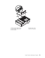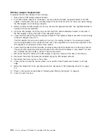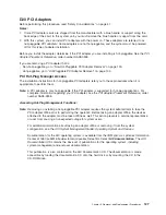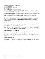
Hot-Swap
Blower
Replacement
Note:
If
a
blower
assembly
is
being
replaced
for
a
redundant
failure,
after
the
service
repair
action
is
completed,
ask
the
customer
to
check
the
crontab
file
for
any
power/cooling
warning
messages.
When
a
power
or
cooling
error
is
encountered,
AIX
adds
an
entry
to
the
crontab
file
to
″
wall
″
a
warning
message
every
12
hours,
to
alert
or
remind
the
customer
of
the
problem.
Replacing
the
faulty
part
does
not
clear
this
crontab
entry,
so
unless
the
crontab
file
is
edited
to
remove
this
entry,
the
customer
continues
to
be
reminded
of
the
failure
despite
its
having
been
repaired.
The
crontab
-l
command
reads
the
crontab
file
to
determine
if
an
entry
exists.
The
crontab
-e
command
edits
the
file.
To
replace
a
hot-swap
blower,
do
the
following:
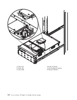
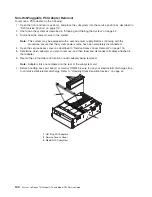
1.
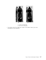
Grasp
the
blower
by
its
snap
button,
and
ensure
that
the
snap
button
is
in
the
unlocked
position.
Note:
Snap
buttons
are
in
the
unlocked
position
when
the
button
component
is
pulled
back
as
far
as
possible.
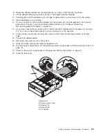
2.
Install
the
two
alignment
tabs
located
on
the
lower
back
edge
of
the
blower
assembly
into
the
two
retaining
slots
located
on
the
chassis
ledge.
3.
Pivoting
from
the
back,
lower
the
front
of
the
blower
onto
its
docking
connector.
4.
Push
down
on
the
front
of
the
blower
until
the
front
flange
of
the
blower
is
seated
on
top
of
the
chassis
ledge.
5.
Push
down
on
the
snap
button,
locking
the
blower
in
place.
6.
Return
the
subsystem
back
to
the
operating
position
as
described
in
“D20
Operating
Position”
on
page
114.
7.
Close
the
rack
door.
Chapter
3.
Removal
and
Replacement
Procedures
121
Summary of Contents for eserver pSeries 7311 D10
Page 1: ...pSeries 7311 Model D10 and Model D20 Service Guide SA38 0627 01 ERserver...
Page 2: ......
Page 3: ...pSeries 7311 Model D10 and Model D20 Service Guide SA38 0627 01 ERserver...
Page 8: ...vi Eserver pSeries 7311 Model D10 and Model D20 Service Guide...
Page 12: ...x Eserver pSeries 7311 Model D10 and Model D20 Service Guide...
Page 14: ...xii Eserver pSeries 7311 Model D10 and Model D20 Service Guide...
Page 25: ...1 Processor Subsystem 2 I O Subsystem Chapter 1 Reference Information 9...
Page 89: ...Chapter 3 Removal and Replacement Procedures 73...
Page 99: ...2 1 1 Top of Cassette 2 Handle Chapter 3 Removal and Replacement Procedures 83...
Page 179: ...D10 I O Subsystem Parts continued 1 2 3 4 5 6 7 Chapter 4 Parts Information 163...
Page 207: ......

