


RIO
Bus
Adapter
Replacement
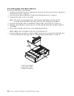
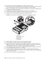
To
replace
the
RIO
bus
adapter,
do
the
following:
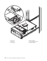
1.
Grasp
the
two
RIO
adapter
release
handles.
2.
Pivot
both
handles
upward
to
90
degrees,
ensuring
that
the
handles
are
perpendicular
to
the
RIO
adapter.
The
handle
cams
have
now
been
placed
into
the
correct
position
to
assist
you
when
seating
the
RIO
adapter
into
its
docking
connector.
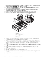
3.
Before
inserting
the
RIO
adapter
into
its
bay,
observe
the
alignment
bracket.
The
alignment
bracket
is
secured
to
the
power
bulkhead.
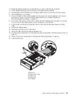
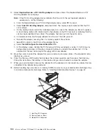
4.
Insert
the
RIO
adapter
into
its
bay.
Ensure
that
the
RIO-2
cable
receptacles
located
on
the
back
of
the
RIO
adapter
is
facing
the
back
of
the
subsystem
chassis.
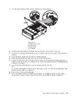
5.
Lower
the
RIO
adapter
through
the
alignment
bracket.
The
alignment
bracket
will
catch
the
back
edge
of
the
RIO
adapter
closest
to
it.
The
RIO
adapter
should
now
be
resting
on
the
top
of
its
docking
connector.
The
docking
connector
has
two
large
alignment
pins
located
on
each
end.
These
alignment
pins
will
ensure
alignment
of
the
RIO
adapter
to
its
docking
connector
when
seated.
6.
Lower
the
RIO
adapter
locking
handles,
carefully
seating
the
RIO
adapter
into
the
docking
connector.
The
plastic
latch
located
beneath
each
handle
clicks
when
the
RIO
adapter
is
fully
seated.
This
click
also
indicates
that
the
handle
is
locked
in
the
closed
position.
7.
Reconnect
the
RIO-2
cables
to
the
RIO
adapter
connectors
located
on
the
back
of
the
chassis.
8.
Reconnect
the
cables
that
were
disconnected
during
the
RIO
adapter
removal.
9.
Reconnect
the
power
source
to
the
system.
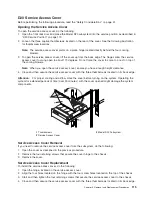
10.
Close
and
then
secure
the
service
access
cover
with
the
three
thumbscrews
located
on
its
back
edge.
11.
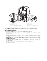
Return
the
Model
D20
to
the
operating
position
as
described
in
“D20
Operating
Position”
on
page
114.
12.
Power
on
the
system
as
described
in
“Stopping
and
Starting
the
System”
on
page
42.
13.
Close
the
rack
front
door.
126
Eserver
pSeries
7311
Model
D10
and
Model
D20
Service
Guide
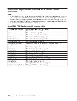
Summary of Contents for eserver pSeries 7311 D10
Page 1: ...pSeries 7311 Model D10 and Model D20 Service Guide SA38 0627 01 ERserver...
Page 2: ......
Page 3: ...pSeries 7311 Model D10 and Model D20 Service Guide SA38 0627 01 ERserver...
Page 8: ...vi Eserver pSeries 7311 Model D10 and Model D20 Service Guide...
Page 12: ...x Eserver pSeries 7311 Model D10 and Model D20 Service Guide...
Page 14: ...xii Eserver pSeries 7311 Model D10 and Model D20 Service Guide...
Page 25: ...1 Processor Subsystem 2 I O Subsystem Chapter 1 Reference Information 9...
Page 89: ...Chapter 3 Removal and Replacement Procedures 73...
Page 99: ...2 1 1 Top of Cassette 2 Handle Chapter 3 Removal and Replacement Procedures 83...
Page 179: ...D10 I O Subsystem Parts continued 1 2 3 4 5 6 7 Chapter 4 Parts Information 163...
Page 207: ......


