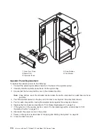


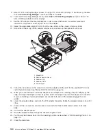

Adding
or
Replacing
a
Non-Hot-Pluggable
PCI
Adapter
To
add
or
replace
an
adapter,
do
the
following:
1.
Open
the
front
and
rear
rack
doors,
and
place
the
system
into
the
service
position
as
described
in
“D20
Service
Position”
on
page
113.
2.
Shut
down
the
system
as
described
in
“Stopping
and
Starting
the
System”
on
page
42.
3.
Disconnect
the
power
source
to
the
system.
Note:
This
system
may
be
equipped
with
a
second
power
supply.
Before
continuing
with
this
procedure,
ensure
that
the
system
has
been
completely
disconnected
from
its
power
source.
4.
Open
the
service
access
cover
as
described
in
“Service
Access
Cover
Removal”
on
page
115.
5.
Refer
to
the
PCI
Adapter
Placement
Reference
for
information
regarding
slot
restrictions
for
adapters
that
can
be
used
in
this
subsystem.
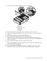
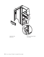
6.
If
necessary,
remove
the
adapter
expansion
slot
shield.
7.
Before
handling
any
card,
board,
or
memory
DIMM,
be
sure
to
use
your
electrostatic
discharge
strap
to
minimize
static-electric
discharge.
Refer
to
“Handling
Static-Sensitive
Devices”
on
page
42.
8.
If
necessary,
remove
the
adapter
from
the
antistatic
package.
Attention:
Avoid
touching
the
components
and
gold-edge
connectors
on
the
adapter.
9.
Place
the
adapter,
component-side
up,
on
a
flat,
static-protective
surface.
10.
Set
any
jumpers
or
switches
as
instructed
by
the
adapter’s
manufacturer.
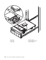
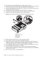
11.
Carefully
grasp
the
adapter
by
its
top
edge,
and
align
the
adapter
with
the
expansion
slot
and
its
connector
on
the
PCI
riser
card.
12.
Press
the
adapter
firmly
into
its
connector.
Attention:
When
you
install
an
adapter
into
your
subsystem,
be
sure
that
it
is
completely
and
correctly
seated
in
its
connector.
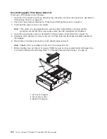
13.
Lower
the
adapter
retaining
seat
onto
the
PCI
adapter
EMC
shield/connector
faceplate.
Rotate
the
adapter
retainer
clip
over
the
adapter
retaining
seat
until
it
comes
to
a
stop.
14.
Close
and
then
secure
the
service
access
cover
with
the
three
thumbscrews
located
on
its
back
edge.
15.
Connect
the
adapter
cables.
16.
Reconnect
the
power
source
to
the
system.
17.
Route
the
cables
through
the
cable-management
arm.
18.
Push
the
system
drawer
back
into
the
operating
position
as
described
in
“D20
Operating
Position”
on
page
114.
19.
Power
on
the
system
as
described
in
“Stopping
and
Starting
the
System”
on
page
42.
20.
Close
the
rack
doors.
132
Eserver
pSeries
7311
Model
D10
and
Model
D20
Service
Guide
Summary of Contents for eserver pSeries 7311 D10
Page 1: ...pSeries 7311 Model D10 and Model D20 Service Guide SA38 0627 01 ERserver...
Page 2: ......
Page 3: ...pSeries 7311 Model D10 and Model D20 Service Guide SA38 0627 01 ERserver...
Page 8: ...vi Eserver pSeries 7311 Model D10 and Model D20 Service Guide...
Page 12: ...x Eserver pSeries 7311 Model D10 and Model D20 Service Guide...
Page 14: ...xii Eserver pSeries 7311 Model D10 and Model D20 Service Guide...
Page 25: ...1 Processor Subsystem 2 I O Subsystem Chapter 1 Reference Information 9...
Page 89: ...Chapter 3 Removal and Replacement Procedures 73...
Page 99: ...2 1 1 Top of Cassette 2 Handle Chapter 3 Removal and Replacement Procedures 83...
Page 179: ...D10 I O Subsystem Parts continued 1 2 3 4 5 6 7 Chapter 4 Parts Information 163...
Page 207: ......


