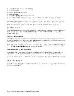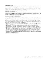
14.
Select
Replace/Remove
a
PCI
Hot-Plug
Adapter
and
press
Enter.
The
Replace/Remove
a
PCI
Hot-Plug
Adapter
menu
displays.
Note:
If
the
PCI
Hot-Plug
Adapter
menu
indicates
that
the
slot
for
the
just
replaced
adapter
is
reading
empty
,
do
the
following:
a.
From
the
Replace/Remove
a
PCI
Hot-Plug
Adapter
menu,
select
F3
to
cancel.
b.
Select
Add
PCI
Hot-Plug
Adapter
,
and
press
Enter.
The
display
screen
indicates
that
the
PCI
slot
is
empty.
c.
On
the
display
screen,
select
the
indicated
empty
slot.
Look
at
the
adapter
you
intend
to
replace.
A
slow
blinking
amber
LED
located
next
to
the
adapter
on
the
PCI
riser
card
is
indicating
that
the
slot
has
been
identified.
Press
Enter.
The
adapter,
has
been
put
into
the
action
state.
d.
Completely
remove
the
hot-plug
adapter
from
the
slot.
The
LED
goes
off.
e.
Reinstall
the
adapter,
ensuring
that
it
is
correctly
seated.
Press
Enter.
f.
Select
F3
to
return
to
the
PCI
Hot-Plug
Adapter
Menu.
g.
Select
Install/Configure
Devices
Added
after
IPL
.
h.
At
the
display
screen,
identify
the
PCI
hot-plug
slot
that
your
adapter
is
using.
If
it
still
shows
as
being
empty,
redo
steps
a
through
g.
However,
before
you
reinstall
the
adapter,
test
it.
If
the
adapter
fails
the
test,
redo
steps
a
through
g
with
a
new
adapter.
15.
Move
the
cursor
to
select
the
adapter
that
you
are
removing
and
press
Enter.
(The
description
entry
displays
as
unknown
).
16.
Press
the
Tab
key
until
the
entry
field
displays
the
remove
operation
and
then
press
the
Enter
key.
Follow
the
instructions
that
display
on
the
screen
until
you
are
instructed
to
remove
the
adapter.
17.
When
you
are
instructed
to
remove
the
adapter
from
the
adapter
slot,
disconnect
any
cables
that
are
connected
to
the
adapter
being
removed.
18.
Before
handling
any
card,
board,
or
memory
DIMM,
be
sure
to
use
your
electrostatic
discharge
strap
to
minimize
static-electric
discharge.
Refer
to
“Handling
Static-Sensitive
Devices”
on
page
42.
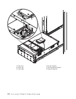
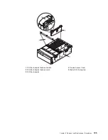
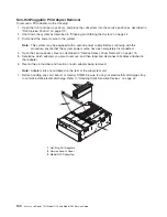
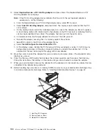
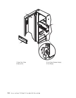
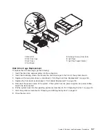
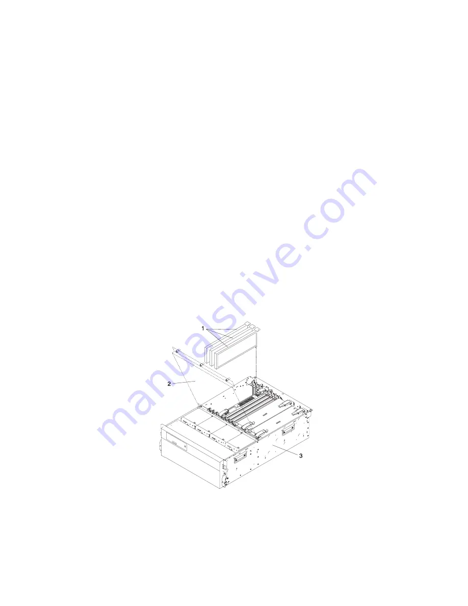
1
Hot-Plug
PCI
Adapters
2
Service
Access
Cover
3
Model
D20
Subsystem
134
Eserver
pSeries
7311
Model
D10
and
Model
D20
Service
Guide
Summary of Contents for eserver pSeries 7311 D10
Page 1: ...pSeries 7311 Model D10 and Model D20 Service Guide SA38 0627 01 ERserver...
Page 2: ......
Page 3: ...pSeries 7311 Model D10 and Model D20 Service Guide SA38 0627 01 ERserver...
Page 8: ...vi Eserver pSeries 7311 Model D10 and Model D20 Service Guide...
Page 12: ...x Eserver pSeries 7311 Model D10 and Model D20 Service Guide...
Page 14: ...xii Eserver pSeries 7311 Model D10 and Model D20 Service Guide...
Page 25: ...1 Processor Subsystem 2 I O Subsystem Chapter 1 Reference Information 9...
Page 89: ...Chapter 3 Removal and Replacement Procedures 73...
Page 99: ...2 1 1 Top of Cassette 2 Handle Chapter 3 Removal and Replacement Procedures 83...
Page 179: ...D10 I O Subsystem Parts continued 1 2 3 4 5 6 7 Chapter 4 Parts Information 163...
Page 207: ......

