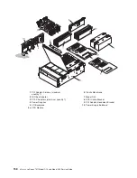
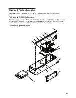

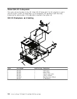

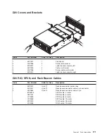
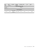
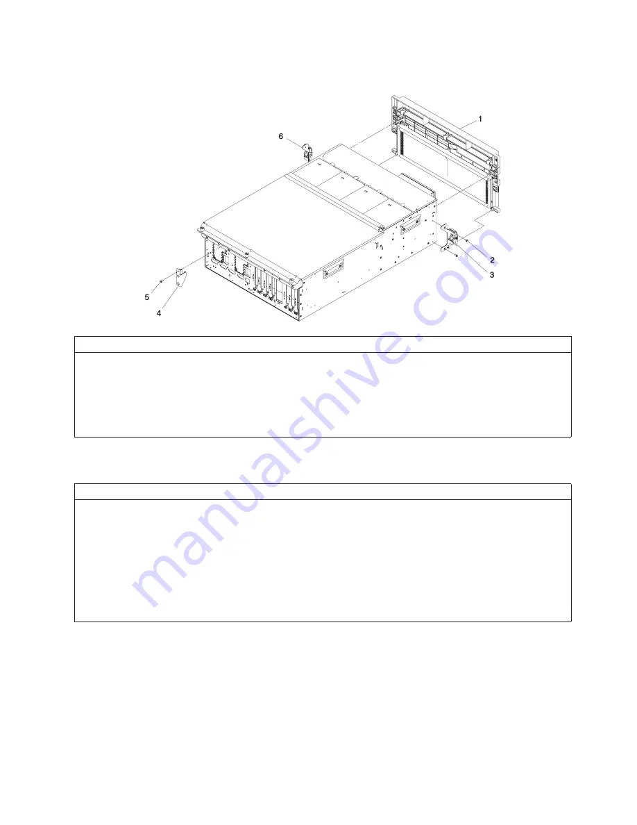
D20
Covers
and
Brackets
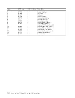
Index
Part
Number
Units
Per
Assy
Description
1
53P1457
1
Front
bezel
2
44H7366
2
Screw,
latch
bracket
3
53P2572
1
Latch
bracket
assembly
left
4
53P0295
4
Cable
arm
bracket
5
44H7366
1
Screw,
cable
arm
bracket
6
53P2573
1
Latch
bracket
assembly
right
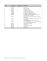
D20
RIO,
SPCN,
and
Rack
Beacon
Cables
Index
Part
Number
Units
Per
Assy
Description
1
53P2231
Up
to
12
Rack
beacon
cable
junction
box
2
53P2237
Up
to
12
Rack
beacon
connector
cable,
4-pin
connector
3
53P2854
Up
to
12
Rack
beacon
connector
cable,
4-pin
87G6235
SPCN
cable,
2
meter
09P1251
SPCN
cable,
3
meter
21F9469
SPCN
cable,
6
meter
21F9358
SPCN
cable,
15
meter
4
53P2676
RIO-2
cable,
3.5
meter
21P5456
RIO-2
cable,
10
meter
Chapter
4.
Parts
Information
171
Summary of Contents for eserver pSeries 7311 D10
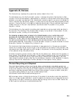
Page 1: ...pSeries 7311 Model D10 and Model D20 Service Guide SA38 0627 01 ERserver...
Page 2: ......
Page 3: ...pSeries 7311 Model D10 and Model D20 Service Guide SA38 0627 01 ERserver...
Page 8: ...vi Eserver pSeries 7311 Model D10 and Model D20 Service Guide...
Page 12: ...x Eserver pSeries 7311 Model D10 and Model D20 Service Guide...
Page 14: ...xii Eserver pSeries 7311 Model D10 and Model D20 Service Guide...
Page 25: ...1 Processor Subsystem 2 I O Subsystem Chapter 1 Reference Information 9...
Page 89: ...Chapter 3 Removal and Replacement Procedures 73...
Page 99: ...2 1 1 Top of Cassette 2 Handle Chapter 3 Removal and Replacement Procedures 83...
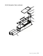
Page 179: ...D10 I O Subsystem Parts continued 1 2 3 4 5 6 7 Chapter 4 Parts Information 163...
Page 207: ......


