Chapter
5.
Fault
and
Attention
LEDs
This
chapter
contains
information
about
fault
and
attention
LEDs,
which
assist
in
identifying
failing
components
in
your
system.
Component
LEDs
Individual
LEDs
are
located
on
or
near
the
failing
components.
The
LEDs
are
located
either
on
the
component
itself
or
on
the
carrier
of
the
component
(for
example,
PCI
adapters
and
disk
drives).
LEDs
are
either
green
or
amber.
Green
LEDs
indicate
one
of
two
things:
v
Electrical
power
is
present.
v
Activity
is
occuring
on
a
link.
(The
system
could
be
sending
or
receiving
information.)
Amber-colored
LEDs
indicate
a
fault
or
identify
condition.
If
your
system
or
one
of
the
components
on
your
system
has
an
amber-colored
LED
turned
on
or
blinking,
identify
the
problem
and
take
the
appropriate
action
to
restore
the
system
to
normal.
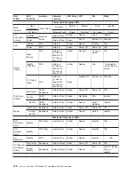
The
following
table
identifies
the
location,
color
and
status
of
your
system
component
LEDs.
173
Summary of Contents for eserver pSeries 7311 D10
Page 1: ...pSeries 7311 Model D10 and Model D20 Service Guide SA38 0627 01 ERserver...
Page 2: ......
Page 3: ...pSeries 7311 Model D10 and Model D20 Service Guide SA38 0627 01 ERserver...
Page 8: ...vi Eserver pSeries 7311 Model D10 and Model D20 Service Guide...
Page 12: ...x Eserver pSeries 7311 Model D10 and Model D20 Service Guide...
Page 14: ...xii Eserver pSeries 7311 Model D10 and Model D20 Service Guide...
Page 25: ...1 Processor Subsystem 2 I O Subsystem Chapter 1 Reference Information 9...
Page 89: ...Chapter 3 Removal and Replacement Procedures 73...
Page 99: ...2 1 1 Top of Cassette 2 Handle Chapter 3 Removal and Replacement Procedures 83...
Page 179: ...D10 I O Subsystem Parts continued 1 2 3 4 5 6 7 Chapter 4 Parts Information 163...
Page 207: ......


