


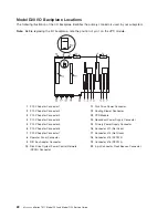
Model
D10
I/O
Subsystem
Locations
This
system
uses
physical
location
codes
to
provide
mapping
of
the
failing
field
replaceable
units.
The
location
codes
are
produced
by
the
processor
subsystem’s
firmware
and
AIX.
For
information
about
how
to
read
a
location
code,
see
the
service
guide
for
the
processor
subsystem
to
which
your
I/O
subsystem
is
connected.
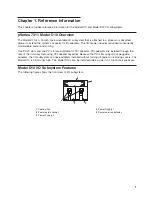
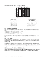
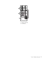
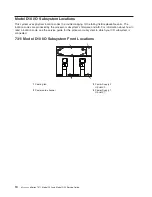
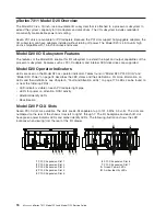
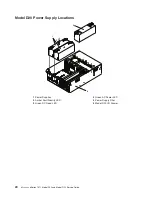
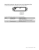
7311
Model
D10
I/O
Subsystem
Front
Locations
1
2
3
4
1
Cooling
fan
3
Power
Supply
2
U0.
dd
-V2
2
Power
cord
channel
4
Power
Supply
1
U0.
dd
-V1
10
Eserver
pSeries
7311
Model
D10
and
Model
D20
Service
Guide
Summary of Contents for eserver pSeries 7311 D10
Page 1: ...pSeries 7311 Model D10 and Model D20 Service Guide SA38 0627 01 ERserver...
Page 2: ......
Page 3: ...pSeries 7311 Model D10 and Model D20 Service Guide SA38 0627 01 ERserver...
Page 8: ...vi Eserver pSeries 7311 Model D10 and Model D20 Service Guide...
Page 12: ...x Eserver pSeries 7311 Model D10 and Model D20 Service Guide...
Page 14: ...xii Eserver pSeries 7311 Model D10 and Model D20 Service Guide...
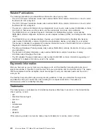
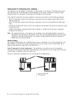
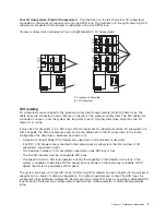
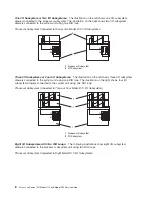
Page 25: ...1 Processor Subsystem 2 I O Subsystem Chapter 1 Reference Information 9...
Page 89: ...Chapter 3 Removal and Replacement Procedures 73...
Page 99: ...2 1 1 Top of Cassette 2 Handle Chapter 3 Removal and Replacement Procedures 83...
Page 179: ...D10 I O Subsystem Parts continued 1 2 3 4 5 6 7 Chapter 4 Parts Information 163...
Page 207: ......


