Model
D20
Reading
the
Operator
Panel
and
I/O
Backplane
LEDs
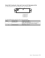
The
following
illustration
shows
the
component
location
on
the
operator
panel
1
Power-On
LED
2
Attention
LED
3
Operator
Panel
4
Snap
Buttons
The
following
table
defines
each
LEDs
function
on
the
operator
panel.
Number
Component
Name
Component
Description
1
Green
Power
LED
Standby
State
-
Blinking
LED
(System
connected
to
power
source
but
not
powered
on.)
Powered
On
-
LED
is
turned
on
solid
(not
blinking).
2
Amber
Attention
LED
Normal
State
-
LED
is
off.
Chapter
1.
Reference
Information
23
Summary of Contents for eserver pSeries 7311 D10
Page 1: ...pSeries 7311 Model D10 and Model D20 Service Guide SA38 0627 01 ERserver...
Page 2: ......
Page 3: ...pSeries 7311 Model D10 and Model D20 Service Guide SA38 0627 01 ERserver...
Page 8: ...vi Eserver pSeries 7311 Model D10 and Model D20 Service Guide...
Page 12: ...x Eserver pSeries 7311 Model D10 and Model D20 Service Guide...
Page 14: ...xii Eserver pSeries 7311 Model D10 and Model D20 Service Guide...
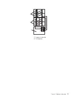
Page 25: ...1 Processor Subsystem 2 I O Subsystem Chapter 1 Reference Information 9...
Page 89: ...Chapter 3 Removal and Replacement Procedures 73...
Page 99: ...2 1 1 Top of Cassette 2 Handle Chapter 3 Removal and Replacement Procedures 83...
Page 179: ...D10 I O Subsystem Parts continued 1 2 3 4 5 6 7 Chapter 4 Parts Information 163...
Page 207: ......

