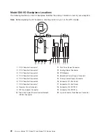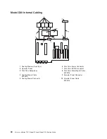
Model
D20
Location
Codes
This
system
(processor
subsystem
and
attached
I/O
subsystems)
uses
physical
location
codes
in
conjunction
with
AIX
location
codes
to
provide
mapping
of
a
failing
field
replaceable
units
(FRUs).
The
location
codes
are
produced
by
the
processor
subsystem’s
firmware
and
AIX.
For
information
about
how
to
read
a
location
code,
see
the
service
guide
for
the
processor
subsystem
to
which
your
I/O
subsystem
is
connected.
AIX
and
Physical
Location
Code
Table
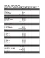
This
section
covers
the
AIX
and
Physical
Location
Code
tables
for
the
Model
D20
I/O
subsystem.
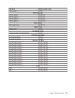
The
tables
in
this
section
contain
the
location
codes
for
I/O
subsystems
when
they
are
attached
to
the
system
unit.
In
the
tables,
the
location
code
for
the
I/O
subsystem
number
is
represented
by
dd
.
The
first
time
that
an
installed
system
is
powered
on,
the
I/O
subsystems
are
numbered.
For
example,
if
a
system
is
first
powered
on
with
two
I/O
subsystems
connected,
then
the
dd
value
for
the
connected
I/O
subsystems
should
be
numbered
from
2
and
3.
Note:
If
the
system
was
powered
on
with
I/O
subsystems
connected
before
delivery
to
the
customer,
the
I/O
subsystem
location
codes
for
the
drawers
connected
at
that
time
are
already
assigned.
If
at
a
later
time,
an
I/O
subsystem
is
removed
from
the
system
and
a
different
I/O
subsystem
is
substituted,
the
substitute
is
assigned
the
next
higher
number
available
for
its
value
of
dd
,
which,
in
the
earlier
example,
is
4.
If
the
original
I/O
subsystem
is
reinstalled
in
the
system
configuration,
the
system
uses
the
original
dd
value
for
the
I/O
subsystem.
To
keep
the
system
from
renumbering
the
I/O
drawer
when
an
I/O
backplane
is
replaced,
the
VPD
module
from
the
old
I/O
backplane
must
be
moved
over
to
the
new
I/O
backplane.
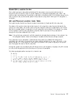
The
following
diagram
defines
each
part
of
a
location
code.
Ux.dd-xx-yy
|
|
|
|
|
|
|
|
|
|
|
yy
This
code
is
used
for
the
next
component
(yy,
yy,
yy,
...)
|
|
xx
This
code
is
used
for
the
next
component
(Px,
Fx,
Vx,
...)
|
dd
This
code
is
the
location
code
for
the
I/O
drawer
(2
to
63)
Ux
This
code
normally
identifies
the
rack
in
which
a
drawer
is
installed.
The
x
will
always
be
zero
(0)
for
this
system.
Chapter
1.
Reference
Information
31
Summary of Contents for eserver pSeries 7311 D10
Page 1: ...pSeries 7311 Model D10 and Model D20 Service Guide SA38 0627 01 ERserver...
Page 2: ......
Page 3: ...pSeries 7311 Model D10 and Model D20 Service Guide SA38 0627 01 ERserver...
Page 8: ...vi Eserver pSeries 7311 Model D10 and Model D20 Service Guide...
Page 12: ...x Eserver pSeries 7311 Model D10 and Model D20 Service Guide...
Page 14: ...xii Eserver pSeries 7311 Model D10 and Model D20 Service Guide...
Page 25: ...1 Processor Subsystem 2 I O Subsystem Chapter 1 Reference Information 9...
Page 89: ...Chapter 3 Removal and Replacement Procedures 73...
Page 99: ...2 1 1 Top of Cassette 2 Handle Chapter 3 Removal and Replacement Procedures 83...
Page 179: ...D10 I O Subsystem Parts continued 1 2 3 4 5 6 7 Chapter 4 Parts Information 163...
Page 207: ......

