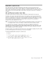
Model
D20
Location
Code
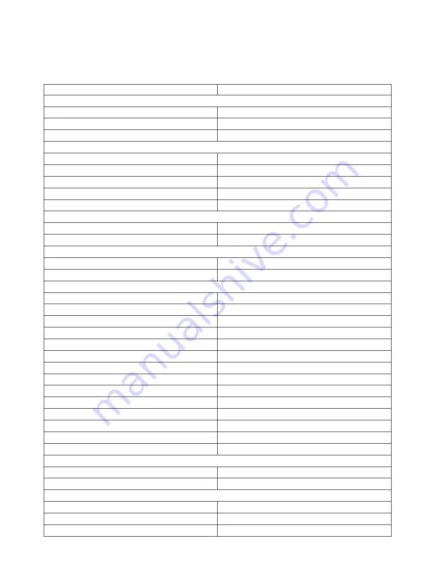
Table
The
following
table
lists
the
location
codes
for
a
model
D20
I/O
subsystem.
The
location
code
for
the
I/O
subsystem
connected
to
a
system
unit
is
U0.
dd
(where
dd
can
be
any
number
from
2
through
63).
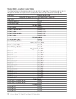
FRU
Name
Physical
Location
Code
Model
D20
I/O
Drawer
U0.
dd
(
dd
=
any
number
from
2
through
63)
Rack
frame
U0
I/O
drawer
backplane
U0.
dd
-P1
I/O
subsystem
drawer
U0.
dd
RIO
Bus
Adapter
RIO
bus
adapter
U0.
dd
-P1.1
RIO
port
1
upper
connector
U0.
dd
-P1.1/Q1
RIO
port
1
cable
U0.
dd
-P1.1/Q1#
RIO
port
0
lower
connector
U0.
dd
-P1.1/Q2
RIO
port
0
cable
U0.
dd
-P1.1/Q2#
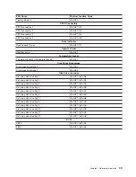
PCI
Bus
Controller
PCI
bus
controller
PHB0
U0.
dd
-P1
PCI
to
PCI
bridge
EADS-X
U0.
dd
-P1
PCI
Bus
Controller
PHB2
PCI
bus
controller
PHB2
U0.
dd
-P1
PCI
to
PCI
bridge
EADS-X
U0.
dd
-P1
Pluggable
Adapter
Slots
PCI
slot
1
U0.
dd
-P1/I1
PCI
card
in
slot
1
U0.
dd
-P1-I1
PCI
slot
2
U0.
dd
-P1/I2
PCI
card
in
slot
2
U0.
dd
-P1-I2
PCI
slot
3
U0.
dd
-P1/I3
PCI
card
in
slot
3
U0.
dd
-P1-I3
PCI
slot
4
U0.
dd
-P1/I4
PCI
card
in
slot
4
U0.
dd
-P1-I4
PCI
slot
5
U0.
dd
-P1/I5
PCI
card
in
slot
5
U0.
dd
-P1/I5
PCI
slot
6
U0.
dd
-P1/I6
PCI
card
in
slot
6
U0.
dd
-P1/I6
PCI
slot
7
U0.
dd
-P1/I7
PCI
card
in
slot
7
U0.
dd
-P1/I7
Power
Supply
Power
supply
1
(no
internal
blower)
U0.
dd
-V1
Power
supply
2
(no
internal
blower)
U0.
dd
-V2
Cooling
Blowers
Cooling
blower
1
U0.
dd
-F1
Cooling
blower
2
U0.
dd
-F2
Cooling
blower
3
U0.
dd
-F3
32
Eserver
pSeries
7311
Model
D10
and
Model
D20
Service
Guide
Summary of Contents for eserver pSeries 7311 D10
Page 1: ...pSeries 7311 Model D10 and Model D20 Service Guide SA38 0627 01 ERserver...
Page 2: ......
Page 3: ...pSeries 7311 Model D10 and Model D20 Service Guide SA38 0627 01 ERserver...
Page 8: ...vi Eserver pSeries 7311 Model D10 and Model D20 Service Guide...
Page 12: ...x Eserver pSeries 7311 Model D10 and Model D20 Service Guide...
Page 14: ...xii Eserver pSeries 7311 Model D10 and Model D20 Service Guide...
Page 25: ...1 Processor Subsystem 2 I O Subsystem Chapter 1 Reference Information 9...
Page 89: ...Chapter 3 Removal and Replacement Procedures 73...
Page 99: ...2 1 1 Top of Cassette 2 Handle Chapter 3 Removal and Replacement Procedures 83...
Page 179: ...D10 I O Subsystem Parts continued 1 2 3 4 5 6 7 Chapter 4 Parts Information 163...
Page 207: ......

