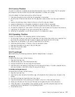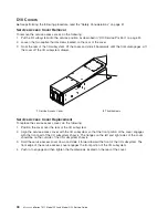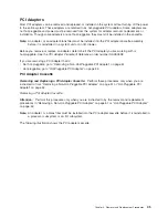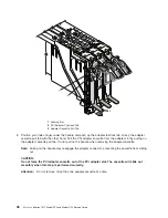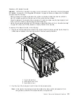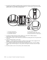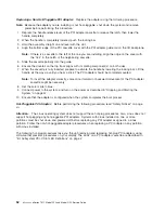
9.
Visually
check
to
ensure
that
the
cassette
is
parallel
with
the
cassettes
to
the
left
or
right.
If
the
cassette
is
not
parallel
with
the
neighboring
cassettes,
the
cassette
dovetail
rails
might
not
be
correctly
engaged.
If
the
cassette
is
not
correctly
aligned,
you
might
need
to
pull
it
out
so
you
can
see
the
ends
of
the
dovetail
rails.
If
so,
reinsert
the
cassette,
ensuring
that
the
dovetail
rails
engage
on
both
sides
of
the
cassette.
Note:
If
there
are
no
other
cassettes
installed,
it
is
not
necessary
to
check
the
alignment
of
the
dovetail
rails.
10.
Depress
the
handle
release
latch.
Lift
the
handle
up
until
the
handle-release
lever
clicks
when
it
locks
into
position.
Note:
To
aid
you
in
seating
the
PCI
adapter
connector,
it
may
be
necessary
to
press
down
on
the
adapter
tailstock
tab.
The
PCI
adapter
is
completely
installed
into
the
PCI
adapter
slot
when
the
handle
is
in
the
fully
raised
position
and
the
tailstock
is
seated
into
the
slots
located
on
the
system
board.
Attention:
Do
not
force
the
handle
into
the
raised
position.
Removing
a
Non-Hot-Pluggable
PCI
Adapter:
To
remove
a
non-hot-pluggable
adapter,
do
the
following:
1.
Turn
off
power
and
remove
the
power
from
the
system
as
described
in
“Stopping
and
Starting
the
System”
on
page
42.
2.
Determine
the
slot
from
which
you
are
removing
the
adapter.
3.
Disconnect
any
cables
that
are
connected
to
the
adapter
being
removed.
4.
Depress
the
handle
release
lever
of
the
PCI
adapter
cassette
to
release
the
latch,
then
lower
the
handle
to
the
down
position.
5.
When
the
handle
is
completely
lowered,
push
in
the
locking
bar.
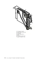
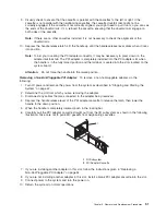
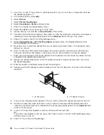
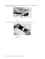
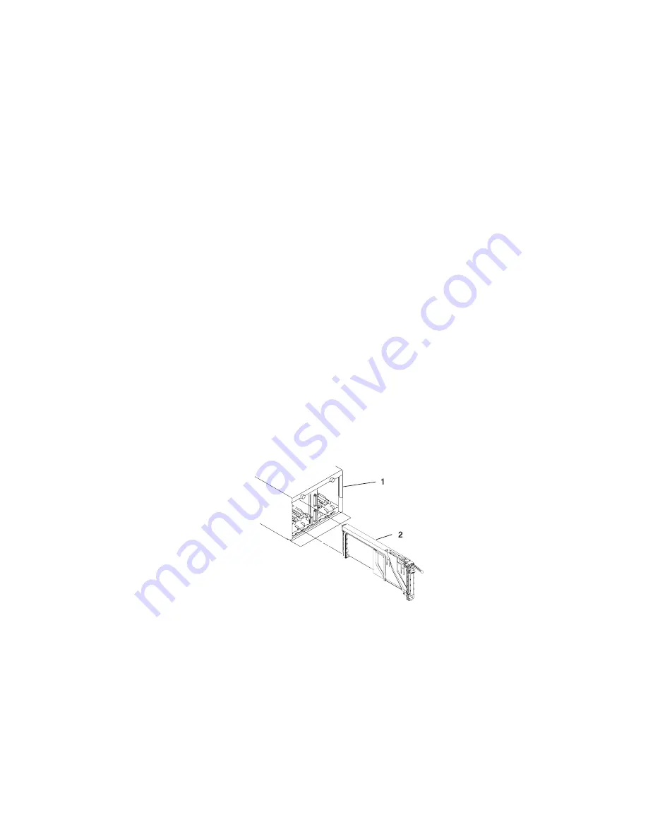
6.
Carefully
pull
the
PCI
adapter
cassette
straight
out
from
the
I/O
subsystem
as
shown
in
the
following
illustration.
Take
care
not
to
pull
EMC
gaskets
from
neighboring
cassettes.
1
I/O
Subsystem
2
PCI
Adapter
Cassette
7.
If
you
are
installing
another
adapter
in
this
slot,
follow
the
instructions
given
in
“Replacing
a
Non-Hot-Pluggable
PCI
Adapter”
on
page
52.
8.
If
you
are
not
installing
another
adapter
in
this
slot,
install
a
blank
PCI
adapter
cassette
into
the
slot.
9.
Connect
power
to
the
system
and
turn
the
power
on.
10.
Return
the
system
to
normal
operations.
Chapter
3.
Removal
and
Replacement
Procedures
51
Summary of Contents for eserver pSeries 7311 D10
Page 1: ...pSeries 7311 Model D10 and Model D20 Service Guide SA38 0627 01 ERserver...
Page 2: ......
Page 3: ...pSeries 7311 Model D10 and Model D20 Service Guide SA38 0627 01 ERserver...
Page 8: ...vi Eserver pSeries 7311 Model D10 and Model D20 Service Guide...
Page 12: ...x Eserver pSeries 7311 Model D10 and Model D20 Service Guide...
Page 14: ...xii Eserver pSeries 7311 Model D10 and Model D20 Service Guide...
Page 25: ...1 Processor Subsystem 2 I O Subsystem Chapter 1 Reference Information 9...
Page 89: ...Chapter 3 Removal and Replacement Procedures 73...
Page 99: ...2 1 1 Top of Cassette 2 Handle Chapter 3 Removal and Replacement Procedures 83...
Page 179: ...D10 I O Subsystem Parts continued 1 2 3 4 5 6 7 Chapter 4 Parts Information 163...
Page 207: ......

