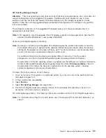
Replacing
a
Non-Hot-Pluggable
PCI
Adapter:
Replace
the
adapter
using
the
following
procedure:
Note:
Because
the
adapter
you
are
installing
is
not
hot-pluggable,
shut
down
the
system
and
remove
power
before
performing
this
procedure.
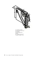
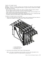
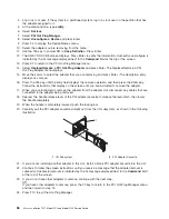
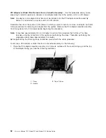
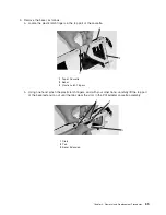
1.
Depress
the
handle
release
lever
of
the
PCI
adapter
cassette
to
release
the
latch,
then
lower
the
handle
completely.
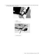
2.
When
the
handle
is
completely
lowered,
push
the
locking
bar.
3.
Hold
the
assembly
straight
on
and
level
with
the
slot.
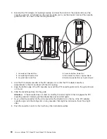
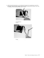
4.
Align
the
bottom
edge
of
the
PCI
cassette
cover
with
the
PCI
adapter
guide
rail
on
the
I/O
backplane.
Note:
If
there
is
a
cassette
to
the
left
of
the
one
you
are
installing,
align
the
ridge
on
the
cover
with
the
″
tick
″
in
the
notch
of
the
neighboring
cassette.
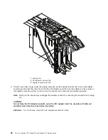
5.
Slide
the
cassette
partially
into
the
guide.
6.
Ensure
the
dovetail
on
the
top
track
aligns
with
its
mating
component(s)
on
both
sides.
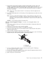
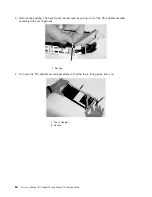
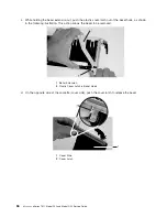
7.
When
the
cassette
is
fully
inserted,
prepare
to
activate
the
handle
by
lowering
the
locking
bar.
Lift
the
handle
all
the
way
up
until
you
hear
a
click.
The
PCI
adapter
should
be
completely
seated.
Note:
To
insert
the
adapter
correctly,
some
minor
forward
or
backward
movement
of
the
PCI
adapter
cassette
might
be
necessary.
8.
Set
the
color
slide
to
blue.
9.
Connect
power
to
the
system,
and
turn
on
the
power
as
described
in
“Stopping
and
Starting
the
System”
on
page
42.
10.
Ensure
that
the
adapter
is
configured
when
the
system
completes
the
boot
process.
Hot-Pluggable
PCI
Adapter:
Before
performing
the
following
procedure,
read
“Safety
Notices”
on
page
vii.
Attention:
The
Linux
operating
system
does
not
support
these
hot-plug
procedures.
Also,
Linux
does
not
support
hot-plugging
any
hot-pluggable
PCI
adapters.
Systems
with
Linux
installed
on
one
or
more
partitions
must
be
shut
down
and
powered
off
before
replacing
any
PCI
adapter
assigned
to
a
Linux
partition.
Follow
the
non-hot-pluggable
adapter
procedures
when
replacing
a
PCI
adapter
in
any
partition
with
Linux
installed.
The
following
hot-plug
procedures
take
you
through
removing
and
replacing
hot-plug
PCI
adapters
using
software
that
presents
procedures
on
your
display.
The
LEDs
on
a
PCI
adapter
cassette
are
described
in
“I/O
Subsystem
PCI-X
Slot
LED
Definitions”
on
page
2.
52
Eserver
pSeries
7311
Model
D10
and
Model
D20
Service
Guide
Summary of Contents for eserver pSeries 7311 D10
Page 1: ...pSeries 7311 Model D10 and Model D20 Service Guide SA38 0627 01 ERserver...
Page 2: ......
Page 3: ...pSeries 7311 Model D10 and Model D20 Service Guide SA38 0627 01 ERserver...
Page 8: ...vi Eserver pSeries 7311 Model D10 and Model D20 Service Guide...
Page 12: ...x Eserver pSeries 7311 Model D10 and Model D20 Service Guide...
Page 14: ...xii Eserver pSeries 7311 Model D10 and Model D20 Service Guide...
Page 25: ...1 Processor Subsystem 2 I O Subsystem Chapter 1 Reference Information 9...
Page 89: ...Chapter 3 Removal and Replacement Procedures 73...
Page 99: ...2 1 1 Top of Cassette 2 Handle Chapter 3 Removal and Replacement Procedures 83...
Page 179: ...D10 I O Subsystem Parts continued 1 2 3 4 5 6 7 Chapter 4 Parts Information 163...
Page 207: ......

