Important:
Although
the
server
supports
a
maximum
of
8
GB
of
system
memory,
some
Microsoft
Windows
operating
systems
recognize
and
support
only
a
lesser
amount
of
system
memory,
as
shown
in
the
following
table.
Windows
operating
system
Maximum
memory
supported
Windows
Server
2003,
Web
Edition
2
GB
Windows
Server
2003,
Standard
Edition
4
GB
v
The
memory
controller
in
the
computer
provides
Chipkill
™
memory
protection
if
the
DIMMs
are
1
GB
or
larger,
or
if
the
computer
is
populated
with
512
MB
x4
DIMMs.
Chipkill
memory
protection
is
a
technology
that
protects
the
computer
from
a
single
chip
failure
on
a
DIMM.
v
The
amount
of
usable
memory
is
reduced
depending
on
the
system
configuration.
A
certain
amount
of
memory
must
be
reserved
for
system
resources.
The
BIOS
displays
the
total
amount
of
installed
memory
and
the
amount
of
configured
memory.
Complete
the
following
steps
to
install
a
DIMM:
1.
Read
the
safety
information
beginning
on
page
v
and
“Installation
guidelines”
on
page
7.
2.
Turn
off
the
server
and
peripheral
devices,
and
disconnect
the
power
cords
and
all
external
cables.
3.
Remove
the
side
cover
(see
“Removing
the
side
cover”
on
page
10).
4.
Remove
the
support
bracket
(see
“Removing
and
installing
the
support
bracket”
on
page
12).
5.
Open
the
microprocessor
air
baffle
(see
“Opening
and
closing
the
microprocessor
air
baffle”
on
page
12).
6.
Locate
the
DIMM
connectors
on
the
system
board
(see
“System-board
option
connectors”
on
page
6
for
the
location
of
the
DIMM
connectors).
Determine
the
connectors
into
which
you
will
install
the
DIMMs.
7.
Install
the
DIMMs
in
the
sequence
shown
in
the
notes
at
the
beginning
of
this
section.
Attention:
To
avoid
breaking
the
retaining
clips
or
damaging
the
DIMM
connectors,
open
and
close
the
clips
gently.
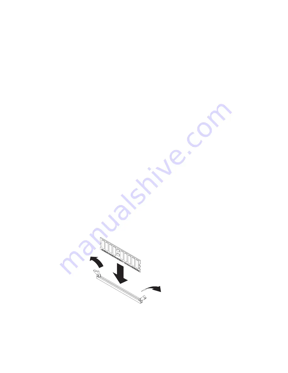
a.
Open
the
retaining
clips
and,
if
necessary,
remove
any
existing
DIMM.
b.
Touch
the
static-protective
package
containing
the
DIMM
to
any
unpainted
metal
surface
on
the
server.
Then,
remove
the
new
DIMM
from
the
package.
c.
Turn
the
DIMM
so
that
the
DIMM
keys
align
correctly
with
the
slot.
d.
Insert
the
DIMM
into
the
connector
by
aligning
the
edges
of
the
DIMM
with
the
slots
at
the
ends
of
the
DIMM
connector.
Firmly
press
the
DIMM
straight
Chapter
2.
Installing
options
15
Summary of Contents for eServer xSeries 226Type 8648
Page 1: ...xSeries 226 Type 8648 Option Installation Guide ERserver...
Page 2: ......
Page 3: ...xSeries 226 Type 8648 Option Installation Guide ERserver...
Page 56: ...44 xSeries 226 Type 8648 Option Installation Guide...
Page 62: ...50 xSeries 226 Type 8648 Option Installation Guide...
Page 70: ...58 xSeries 226 Type 8648 Option Installation Guide...
Page 74: ...62 xSeries 226 Type 8648 Option Installation Guide...
Page 75: ......
Page 76: ...Part Number 88P8978 Printed in USA 1P P N 88P8978...


