background image

v


Do


not


leave


the


device


where


others


can


handle


and


damage


it.


v


While


the


device


is


still


in


its


static-protective


package,


touch


it


to


an


unpainted


metal


part


of


the


server


for


at


least


2


seconds.


This


drains


static


electricity


from


the


package


and


from


your


body.


v


Remove


the


device


from


its


package


and


install


it


directly


into


the


server


without


setting


down


the


device.


If


it


is


necessary


to


set


down


the


device,


put


it


back


into


its


static-protective


package.


Do


not


place


the


device


on


your


server


cover


or


on


a


metal


surface.


v


Take


additional


care


when


handling


devices


during


cold


weather.


Heating


reduces


indoor


humidity


and


increases


static


electricity.

Server


power


features


When


the


server


is


connected


to


an


ac


power


source


but


is


not


turned


on,


the


operating


system


does


not


run,


and


all


core


logic


except


for


the


service


processor


is


shut


down;


however,


the


server


can


respond


to


requests


from


the


service


processor,


such


as


a


remote


request


to


turn


on


the


server.


The


power-on


LED


flashes


to


indicate


that


the


server


is


connected


to


ac


power


but


is


not


turned


on.


Turning


on


the


server


Approximately


20


seconds


after


the


server


is


connected


to


ac


power,


the


power-control


button


becomes


active,


and


you


can


turn


on


the


server


and


start


the


operating


system


by


pressing


the


power-control


button.


The


server


can


also


be


turned


on


in


any


of


the


following


ways:


v


If


a


power


failure


occurs


while


the


server


is


turned


on,


the


server


will


restart


automatically


when


power


is


restored.


v


If


the


server


is


connected


to


an


Advanced


System


Management


interconnect


network


that


contains


at


least


one


server


with


an


optional


Remote


Supervisor


Adapter


II


installed,


the


server


can


be


turned


on


from


the


Remote


Supervisor


Adapter


II


user


interface.


v


If


your


operating


system


supports


the


system-management


software


for


an


optional


Remote


Supervisor


Adapter


II,


the


system-management


software


can


turn


on


the


server.


v


If


your


operating


system


supports


the


Wake


on


LAN

®


feature,


the


Wake


on


LAN


feature


can


turn


on


the


server.

Note:


When


4


GB


or


more


of


memory


(physical


or


logical)


is


installed,


some


memory


is


reserved


for


various


system


resources


and


is


unavailable


to


the


operating


system.


The


amount


of


memory


that


is


reserved


for


system


resources


depends


on


the


operating


system,


the


configuration


of


the


server,


and


the


configured


PCI


options.


Turning


off


the


server


When


you


turn


off


the


server


and


leave


it


connected


to


ac


power,


the


server


can


respond


to


requests


from


the


service


processor,


such


as


a


remote


request


to


turn


on


the


server.


To


remove


all


power


from


the


server,


you


must


disconnect


it


from


the


power


source.


Some


operating


systems


require


an


orderly


shutdown


before


you


turn


off


the


server.


See


your


operating-system


documentation


for


information


about


shutting


down


the


operating


system.


8


xSeries


306


Type


8836:


Option


Installation


Guide

Summary of Contents for eServer xSeries 306 Type 8836

Page 1: ...xSeries 306 Type 8836 Option Installation Guide ERserver...

Page 2: ......

Page 3: ...xSeries 306 Type 8836 Option Installation Guide ERserver...

Page 4: ...e general information in Notices on page 23 First Edition April 2004 Copyright International Business Machines Corporation 2004 All rights reserved US Government Users Restricted Rights Use duplicatio...

Page 5: ...stalling a memory module 15 Replacing a fan assembly 16 Replacing the battery 17 Completing the installation 18 Installing the cover 19 Connecting the cables 19 Updating the server configuration 20 Ch...

Page 6: ...Chinese Class A warning statement 27 Japanese Voluntary Control Council for Interference VCCI statement 27 Power cords 28 Index 31 iv xSeries 306 Type 8836 Option Installation Guide...

Page 7: ...alleert eerst de veiligheidsvoorschriften Ennen kuin asennat t m n tuotteen lue turvaohjeet kohdasta Safety Information Avant d installer ce produit lisez les consignes de s curit Vor der Installation...

Page 8: ...Antes de instalar este producto lea la informaci n de seguridad L s s kerhetsinformationen innan du installerar den h r produkten vi xSeries 306 Type 8836 Option Installation Guide...

Page 9: ...r reconfiguration of this product during an electrical storm v Connect all power cords to a properly wired and grounded electrical outlet v Connect to properly wired outlets any equipment that will be...

Page 10: ...tement 3 CAUTION When laser products such as CD ROMs DVD drives fiber optic devices or transmitters are installed note the following v Do not remove the covers Removing the covers of the laser product...

Page 11: ...power control button on the device and the power switch on the power supply do not turn off the electrical current supplied to the device The device also might have more than one power cord To remove...

Page 12: ...l attached Hazardous voltage current and energy levels are present inside any component that has this label attached There are no serviceable parts inside these components If you suspect a problem wit...

Page 13: ...ion document v Rack Installation Instructions This printed document contains instructions for installing your server in a rack v Hardware Maintenance Manual and Troubleshooting Guide This document is...

Page 14: ...ou avoid inconvenient or problem situations v Attention These notices indicate possible damage to programs devices or data An attention notice is placed just before the instruction or situation in whi...

Page 15: ...hot swap capability you can remove or install the component while the server is running Orange can also indicate touch points on hot swap components See the instructions for removing or installing a...

Page 16: ...Primary IDE connector Microprocessor power cable connector Power connector Fan 3 connector Fan 4 connector Fan 2 connector Fan 1 connector SATA connectors Wake on LAN connector SCSI LED connector Micr...

Page 17: ...connector Video connector Keyboard mouse connector Serial connector System board LEDs The following illustration shows the light emitting diodes LEDs on the system board DIMM 4 error LED DIMM 3 error...

Page 18: ...ons DIMM 1 slot DIMM 2 slot DIMM 3 slot DIMM 4 slot PCI X riser card connector Battery connector The following illustration shows the location of the PCI X slots on the riser card assembly PCI X slot...

Page 19: ...running Orange can also indicate touch points on hot swap components See the instructions for removing or installing a specific hot swap component for any additional procedures that you might have to...

Page 20: ...lso be turned on in any of the following ways v If a power failure occurs while the server is turned on the server will restart automatically when power is restored v If the server is connected to an...

Page 21: ...supports this feature v If the operating system stops functioning you can press and hold the power control button for more than 4 seconds to turn off the server v If the server is connected to an Adv...

Page 22: ...height three quarter length adapter in expansion slot 2 v Your server supports 3 3 V or universal adapters v Your server uses a rotational interrupt technique to configure PCI X adapters so that you c...

Page 23: ...eps to install an adapter Riser card assembly PCI X slots Adapter support bracket Adapter PCI X riser card connector 1 Read the safety information beginning on page v and Installation guidelines on pa...

Page 24: ...you turn on the server Incomplete insertion might cause damage to the system board or the adapter 9 To install the adapter in the riser card assembly carefully grasp the adapter by its top edge or upp...

Page 25: ...drive SATA hard disk drive connector 1 Read the safety information beginning on page v and Installation guidelines on page 7 2 Turn off the server and peripheral devices and disconnect the power cord...

Page 26: ...ver and peripheral devices and disconnect the power cord and all external cables Remove the cover see Removing the cover on page 9 3 Press the release tabs on the bezel and pull the bezel away from th...

Page 27: ...e the same size speed type and technology as the DIMM installed in DIMM connector 1 You can mix compatible DIMMs from various manufacturers v If you install a second pair of DIMMs in DIMM connectors 2...

Page 28: ...you have other options to install do so now Otherwise go to Completing the installation on page 18 Replacing a fan assembly The server comes with four replaceable fans Complete the following steps to...

Page 29: ...eplacing the lithium battery use only IBM Part Number 33F8354 or an equivalent type battery recommended by the manufacturer If your system has a module containing a lithium battery replace it only wit...

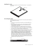
Page 30: ...server for detailed information about how to install the server in a rack cabinet Attention v Install your server only in a rack cabinet with perforated doors v Do not leave open space above or below...

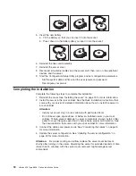
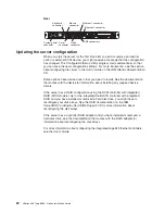
Page 31: ...stem installed see the documentation that comes with your software for additional cabling instructions 5 There is one keyboard connector on the back of the server Use this connector to connect the ser...

Page 32: ...he documentation that comes with the device for information about installing any required device drivers If the server has a RAID configuration using the SCSI controller with integrated RAID SCSI mode...

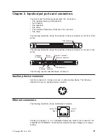
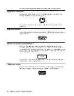
Page 33: ...ver Ethernet 2 connector Ethernet 1 connector USB connectors Mouse connector Keyboard connector Serial connector Video connector The following sections describe these connectors Auxiliary device conne...

Page 34: ...Universal Serial Bus USB connector to connect a USB device USB technology transfers data at up to 12 Mb per second Mbps with a maximum of 127 devices and a maximum signal distance of 5 meters 16 ft p...

Page 35: ...Y OF ANY KIND EITHER EXPRESS OR IMPLIED INCLUDING BUT NOT LIMITED TO THE IMPLIED WARRANTIES OF NON INFRINGEMENT MERCHANTABILITY OR FITNESS FOR A PARTICULAR PURPOSE Some states do not allow disclaimer...

Page 36: ...emarks of Intel Corporation in the United States other countries or both Microsoft Windows and Windows NT are trademarks of Microsoft Corporation in the United States other countries or both UNIX is a...

Page 37: ...functionality Product recycling and disposal This unit contains materials such as circuit boards cables electromagnetic compatibility gaskets and connectors which may contain lead and copper berylliu...

Page 38: ...ables and connectors or by unauthorized changes or modifications to this equipment Unauthorized changes or modifications could void the user s authority to operate the equipment This device complies w...

Page 39: ...has been tested and found to comply with the limits for Class A Information Technology Equipment according to CISPR 22 European Standard EN 55022 The limits for Class A equipment were derived for comm...

Page 40: ...part number Used in these countries and regions 02K0546 China 13F9940 Australia Fiji Kiribati Nauru New Zealand Papua New Guinea 13F9979 Afghanistan Albania Algeria Andorra Angola Armenia Austria Aze...

Page 41: ...s Barbados Belize Bermuda Bolivia Brazil Caicos Islands Canada Cayman Islands Costa Rica Colombia Cuba Dominican Republic Ecuador El Salvador Guam Guatemala Haiti Honduras Jamaica Japan Mexico Microne...

Page 42: ...30 xSeries 306 Type 8836 Option Installation Guide...

Page 43: ...installation 15 N notes important 24 notices attention 2 book 2 caution 2 danger 2 electronic emission 26 FCC Class A 26 important 2 O order of installation memory modules 15 P power cords 28 R relate...

Page 44: ...32 xSeries 306 Type 8836 Option Installation Guide...

Page 45: ......

Page 46: ...Part Number 59P6591 Printed in USA 1P P N 59P6591...

Reviews: