


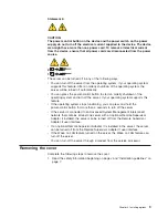
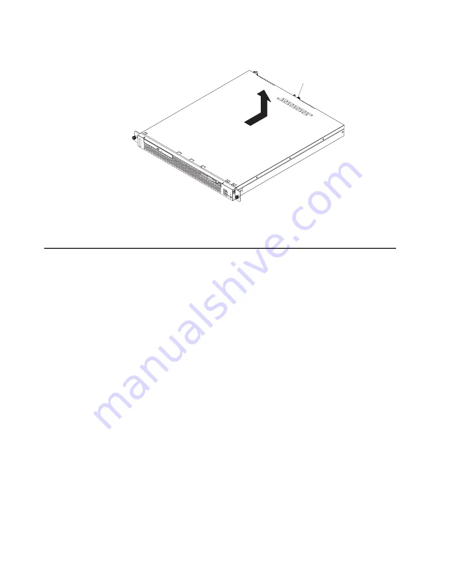
2.
Turn
off
the
server
and
all
attached
devices
(see
“Turning
off
the
server”
on
page
8).
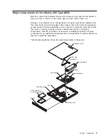
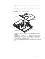
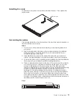
Captive screw
3.
Disconnect
all
external
cables
and
the
power
cord.
4.
Loosen
the
captive
screw
on
the
rear
of
the
cover.
5.
Slide
the
cover
back
and
off
the
server.
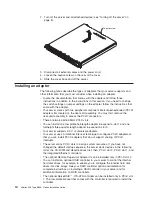
Installing
an
adapter
The
following
notes
describe
the
types
of
adapters
that
your
server
supports
and
other
information
that
you
must
consider
when
installing
an
adapter:
v
Locate
the
documentation
that
comes
with
the
adapter
and
follow
those
instructions
in
addition
to
the
instructions
in
this
section.
If
you
need
to
change
the
switch
settings
or
jumper
settings
on
the
adapter,
follow
the
instructions
that
come
with
the
adapter.
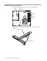
v
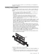
Your
server
comes
with
two
peripheral
component
interconnect-extended
(PCI-X)
adapter
slots
located
on
the
riser-card
assembly.
You
must
first
remove
the
riser-card
assembly
to
access
the
PCI-X
connectors.
v
There
are
two
64-bit
66
MHz
PCI-X
slots.
v
You
can
install
one
low
profile
half-length
adapter
in
expansion
slot
1
and
one
full-height
three-quarter-length
adapter
in
expansion
slot
2.
v
Your
server
supports
3.3
V
or
universal
adapters.
v
Your
server
uses
a
rotational
interrupt
technique
to
configure
PCI-X
adapters
so
that
you
can
install
PCI-X
adapters
that
do
not
support
sharing
of
PCI-X
interrupts.
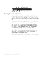
v
The
server
scans
PCI-X
slots
to
assign
system
resources.
If
you
have
not
changed
the
default
startup
sequence,
the
server
starts
devices
in
the
following
order:
the
CD-ROM
and
diskette
drives
first;
then,
PCI-X
slot
2,
PCI-X
slot
1,
and
the
integrated
Ethernet
controllers.
v
The
optional
Remote
Supervisor
Adapter
II
can
be
installed
only
in
PCI-X
slot
2.
v
You
can
install
an
optional
RAID
controller
in
your
server
to
control
the
internal
hard
disk
drives,
for
example,
to
enable
you
to
configure
the
internal
hard
disk
drives
into
disk
arrays.
See
your
RAID
controller
option
documentation
for
complete
instructions
on
installing
a
RAID
controller
in
your
server
and
for
additional
information
on
RAID
controllers.
v
The
optional
ServeRAID
™
-7t
S-ATA
controller
can
be
installed
only
in
PCI-X
slot
1.
The
low-profile
bracket
that
comes
with
the
controller
is
required
to
install
the
controller.
10
xSeries
306
Type
8836:
Option
Installation
Guide
Summary of Contents for eServer xSeries 306 Type 8836
Page 1: ...xSeries 306 Type 8836 Option Installation Guide ERserver...
Page 2: ......
Page 3: ...xSeries 306 Type 8836 Option Installation Guide ERserver...
Page 42: ...30 xSeries 306 Type 8836 Option Installation Guide...
Page 44: ...32 xSeries 306 Type 8836 Option Installation Guide...
Page 45: ......
Page 46: ...Part Number 59P6591 Printed in USA 1P P N 59P6591...


