


Note:
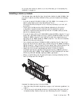
Correct
airflow
is
from
the
front
to
the
rear
of
the
server.
6.
Install
the
replacement
fan
in
the
location
from
which
you
removed
the
failed
fan.
7.
Connect
the
replacement
fan
cable
to
the
system
board.
If
you
have
other
options
to
install,
do
so
now.
Otherwise,
go
to
“Completing
the
installation”
on
page
18.
Replacing
the
battery
When
replacing
the
battery,
you
must
replace
it
with
a
lithium
battery
of
the
same
type
from
the
same
manufacturer.
To
avoid
possible
danger,
read
and
follow
the
safety
statement
below.
To
order
replacement
batteries,
call
1-800-772-2227
within
the
United
States,
and
1-800-465-7999
or
1-800-465-6666
within
Canada.
Outside
the
U.S.
and
Canada,
call
your
IBM
reseller
or
IBM
marketing
representative.
Note:
After
you
replace
the
battery,
you
must
reconfigure
your
system
and
reset
the
system
date
and
time.
Statement
2:
CAUTION:
When
replacing
the
lithium
battery,
use
only
IBM
Part
Number
33F8354
or
an
equivalent
type
battery
recommended
by
the
manufacturer.
If
your
system
has
a
module
containing
a
lithium
battery,
replace
it
only
with
the
same
module
type
made
by
the
same
manufacturer.
The
battery
contains
lithium
and
can
explode
if
not
properly
used,
handled,
or
disposed
of.
Do
not:
v
Throw
or
immerse
into
water
v
Heat
to
more
than
100°C
(212°F)
v
Repair
or
disassemble
Dispose
of
the
battery
as
required
by
local
ordinances
or
regulations.
Complete
the
following
steps
to
replace
the
battery:
1.
Read
the
safety
information
beginning
on
page
v
and
follow
any
special
handling
and
installation
instructions
supplied
with
the
replacement
battery.
2.
Turn
off
the
server
and
peripheral
devices,
and
disconnect
the
power
cord
and
all
external
cables.
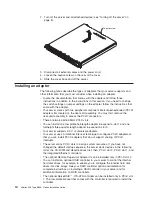
Remove
the
cover
(see
“Removing
the
cover”
on
page
9).
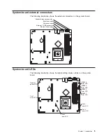
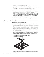
3.
Remove
the
riser-card
assembly.
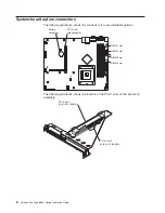
4.
Remove
the
battery:
a.
Press
the
battery
release
tab
to
release
the
battery
from
the
socket.
b.
Lift
the
battery
out
of
the
socket.
Chapter
2.
Installing
options
17
Summary of Contents for eServer xSeries 306 Type 8836
Page 1: ...xSeries 306 Type 8836 Option Installation Guide ERserver...
Page 2: ......
Page 3: ...xSeries 306 Type 8836 Option Installation Guide ERserver...
Page 42: ...30 xSeries 306 Type 8836 Option Installation Guide...
Page 44: ...32 xSeries 306 Type 8836 Option Installation Guide...
Page 45: ......
Page 46: ...Part Number 59P6591 Printed in USA 1P P N 59P6591...


