
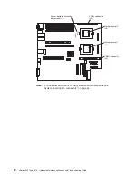
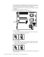
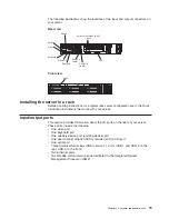
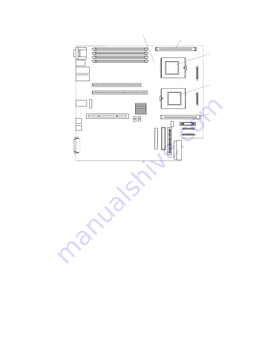
VRM 2 connector
(J5)
VRM 1 connector
(J8)
Microprocessor 2
(J6)
Microprocessor 1
(J7)
533MHz
FSB CPU
ONL
Y
System-board identification
(some models)
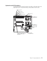
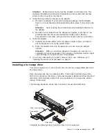
Note:
For additional illustrations of the system-board components, see
“System-board option connectors” on page 44.
62
xSeries 345 Type 8670: Hardware Maintenance Manual and Troubleshooting Guide
Summary of Contents for eServer xSeries 345 Type 8670
Page 1: ...xSeries 345 Type 8670 Hardware Maintenance Manual and Troubleshooting Guide ERserver...
Page 2: ......
Page 3: ...xSeries 345 Type 8670 Hardware Maintenance Manual and Troubleshooting Guide ERserver...
Page 6: ...iv xSeries 345 Type 8670 Hardware Maintenance Manual and Troubleshooting Guide...
Page 10: ...viii xSeries 345 Type 8670 Hardware Maintenance Manual and Troubleshooting Guide...
Page 18: ...8 xSeries 345 Type 8670 Hardware Maintenance Manual and Troubleshooting Guide...
Page 88: ...78 xSeries 345 Type 8670 Hardware Maintenance Manual and Troubleshooting Guide...
Page 124: ...114 xSeries 345 Type 8670 Hardware Maintenance Manual and Troubleshooting Guide...
Page 130: ...120 xSeries 345 Type 8670 Hardware Maintenance Manual and Troubleshooting Guide...
Page 141: ...Chapter 8 Related service information 131...
Page 142: ...132 xSeries 345 Type 8670 Hardware Maintenance Manual and Troubleshooting Guide...
Page 143: ...Chapter 8 Related service information 133...
Page 144: ...134 xSeries 345 Type 8670 Hardware Maintenance Manual and Troubleshooting Guide...
Page 145: ...Chapter 8 Related service information 135...
Page 146: ...136 xSeries 345 Type 8670 Hardware Maintenance Manual and Troubleshooting Guide...
Page 147: ...Chapter 8 Related service information 137...
Page 157: ...Chapter 8 Related service information 147...
Page 158: ...148 xSeries 345 Type 8670 Hardware Maintenance Manual and Troubleshooting Guide...
Page 159: ...Chapter 8 Related service information 149...
Page 160: ...150 xSeries 345 Type 8670 Hardware Maintenance Manual and Troubleshooting Guide...
Page 161: ...Chapter 8 Related service information 151...
Page 162: ...152 xSeries 345 Type 8670 Hardware Maintenance Manual and Troubleshooting Guide...
Page 166: ...156 xSeries 345 Type 8670 Hardware Maintenance Manual and Troubleshooting Guide...
Page 174: ...164 xSeries 345 Type 8670 Hardware Maintenance Manual and Troubleshooting Guide...
Page 175: ......
Page 176: ...Part Number 48P9718 1P P N 48P9718...


