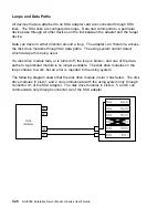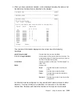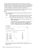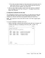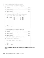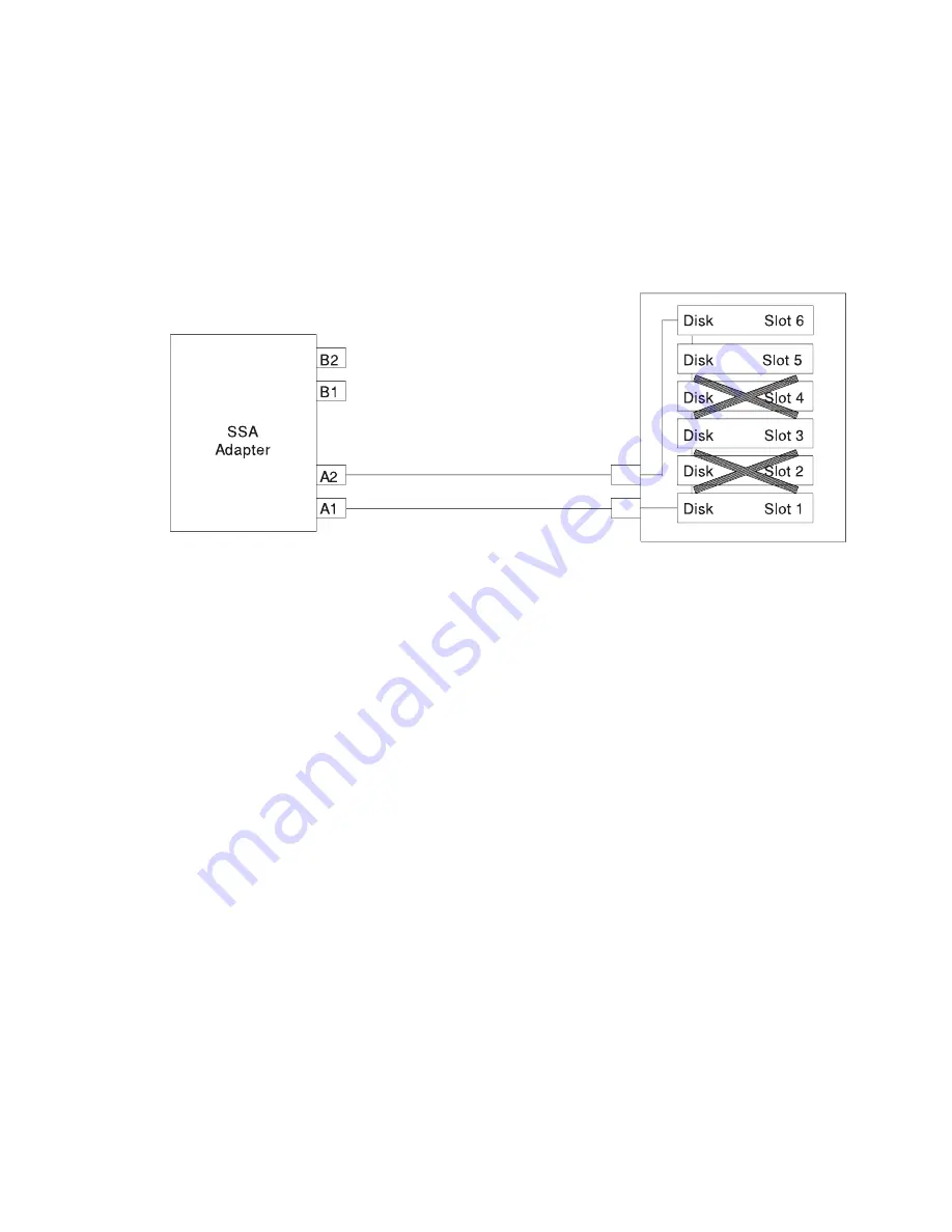
If two or more disk drive modules are turned off, fail, or are removed from the loop,
some modules might become isolated from the SSA adapter.
The following diagram shows that the disk drive modules in slots 2 and 4 have failed.
The disk drive module in slot 1 can communicate with the using system only through
connector A1 of the SSA adapter. The disk drive module in slots 5 and 6 can com-
municate with the using system only through connector A2 of the SSA adapter. The
disk drive module in slot 3 is isolated from the SSA adapter.
Chapter 7. Using the Service Aids
7-29
Summary of Contents for H SERIES RS/6000
Page 1: ...RS 6000 Enterprise Server Model H Series IBM User s Guide SA38 0546 01...
Page 14: ...xiv RS 6000 Enterprise Server Model H Series User s Guide...
Page 16: ...xvi RS 6000 Enterprise Server Model H Series User s Guide...
Page 128: ...5 16 RS 6000 Enterprise Server Model H Series User s Guide...
Page 147: ...Chapter 6 Using the Online and Standalone Diagnostics 6 19...
Page 160: ...6 32 RS 6000 Enterprise Server Model H Series User s Guide...
Page 265: ...expect 8 r or 7 r or 6 r or 4 r or 3 r delay 2 done Appendix C Modem Configurations C 21...
Page 272: ...C 28 RS 6000 Enterprise Server Model H Series User s Guide...
Page 276: ...D 4 RS 6000 Enterprise Server Model H Series User s Guide...
Page 285: ...Index X 9...
Page 286: ...X 10 RS 6000 Enterprise Server Model H Series User s Guide...
Page 289: ......

