


Updating Firmware from AIX
You must delete the file /var/update_flash_image before proceeding.
The flash update image file must have already been placed in the /var file system.
This could have been done with a file transfer from another server or with the
dosread command of the AIX DOS Utilities. For example, with the flash update
image in place, issuing the following AIX command
shutdown -u /var/\filename\.img
initiates the update process. Where *filename* is the name of the flash update
image. During the process, the server powers down and reboots. The process is
complete when the login prompt reappears.
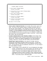
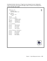
Service Processor Logs
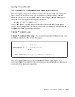
Service Processor Error Log:
The Service Processor error logs contain error
conditions detected by the Service Processor.
à
ð
Error Log
1997ð626223337
ð. Loss of Redundant Fan #5
4ð21ðð91
Press "C" to clear error log, any other key to continue.
>
á
ñ
The time stamp in this error log is Coordinated Universal Time (CUT), a.k.a.
Greenwich Mean Time (GMT). AIX error logs have more information available and
are able to time stamp with local time.
Chapter 3. Service Processor Menus
3-33
Summary of Contents for H SERIES RS/6000
Page 1: ...RS 6000 Enterprise Server Model H Series IBM User s Guide SA38 0546 01...
Page 14: ...xiv RS 6000 Enterprise Server Model H Series User s Guide...
Page 16: ...xvi RS 6000 Enterprise Server Model H Series User s Guide...
Page 128: ...5 16 RS 6000 Enterprise Server Model H Series User s Guide...
Page 147: ...Chapter 6 Using the Online and Standalone Diagnostics 6 19...
Page 160: ...6 32 RS 6000 Enterprise Server Model H Series User s Guide...
Page 265: ...expect 8 r or 7 r or 6 r or 4 r or 3 r delay 2 done Appendix C Modem Configurations C 21...
Page 272: ...C 28 RS 6000 Enterprise Server Model H Series User s Guide...
Page 276: ...D 4 RS 6000 Enterprise Server Model H Series User s Guide...
Page 285: ...Index X 9...
Page 286: ...X 10 RS 6000 Enterprise Server Model H Series User s Guide...
Page 289: ......


