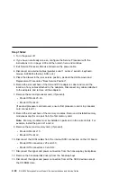
14. Disconnect the diskette drive cable from the diskette drive connector J13 on the
I/O board.
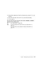
15. Plug in the power cable and wait for OK on the operator panel display.
16. Turn the power on.
Does the system stop with code E1F2, E1F3, STBY, 20EE000B or 4BA00830
displayed on the operator panel?
NO
Go to “Step 1540-3” on page 2-40.
YES
If a second processor card was removed go to “Step 1540-4” on
page 2-41.
If the system has only one processor card go to “Step 1540-5” on
page 2-42.
Chapter 2. Maintenance Analysis Procedures
2-39
Summary of Contents for H SERIES RS/6000
Page 1: ...RS 6000 Enterprise Server Model H Series IBM Installation and Service Guide SA38 0547 01...
Page 14: ...xiv RS 6000 Enterprise Server Model H Series Installation and Service Guide...
Page 34: ...1 18 RS 6000 Enterprise Server Model H Series Installation and Service Guide...
Page 106: ...2 72 RS 6000 Enterprise Server Model H Series Installation and Service Guide...
Page 178: ...3 72 RS 6000 Enterprise Server Model H Series Installation and Service Guide...
Page 262: ...7 14 RS 6000 Enterprise Server Model H Series Installation and Service Guide...
Page 279: ...Chapter 7 Removal and Replacement Procedures 7 31...
Page 315: ...Chapter 8 Parts Information Chapter 8 Parts Information 8 1...
Page 328: ...8 14 RS 6000 Enterprise Server Model H Series Installation and Service Guide...
Page 340: ...A 12 RS 6000 Enterprise Server Model H Series Installation and Service Guide...
Page 401: ...expect 8 r or 7 r or 6 r or 4 r or 3 r delay 2 done Appendix E Modem Configurations E 21...
Page 408: ...E 28 RS 6000 Enterprise Server Model H Series Installation and Service Guide...
Page 412: ...F 4 RS 6000 Enterprise Server Model H Series Installation and Service Guide...
Page 419: ...Index X 7...
Page 420: ...X 8 RS 6000 Enterprise Server Model H Series Installation and Service Guide...
Page 423: ......


