YES
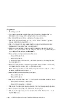
Repeat this step, adding one SCSI device at a time, until all the SCSI
devices that were attached to integrated SCSI adapter connector (port 1),
except the hot-swap bay backplanes, are connected and tested.
Go to “Step 1540-12.”
Step 1540-12
The system is working correctly with this configuration. One of the hot-swap bay
backplanes may be defective.
1. Make sure the diagnostic CD-ROM is inserted into the CD-ROM drive.
2. Turn the power off and remove the power cable.
3. Connect the signal and power connectors to the backplane in hot swap bay C.
4. Plug in the power cable and wait for OK on the operator panel display.
5. Turn the power on.
6. After the keyboard indicator is displayed, press the F5 key on the directly-
attached keyboard or the number 5 key on an ASCII terminal keyboard.
7. Enter the appropriate password if prompted to do so.
Is the "Please define the System Console" screen displayed?
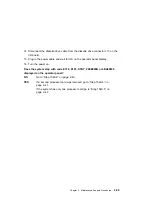
NO
One of the FRUs remaining in the system unit is defective.
In the following order, exchange the FRUs that have not been exchanged:
1. SCSI cable
2. Hot-swap bay backplane
3. Power distribution board
Repeat this step until the defective FRU is identified or all the FRUs have
been exchanged.
If the symptom did not change and all the FRUs have been exchanged,
call your service support person for assistance.
If the symptom has changed, check for loose cards, cables, and obvious
problems. If you do not find a problem return to “Step 1540-1” on
page 2-37 in this MAP and follow the instructions for the new symptom.
YES
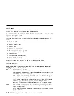
If a second hot swap bay backplane is installed in hot swap bay D, go to
“Step 1540-13” on page 2-50.
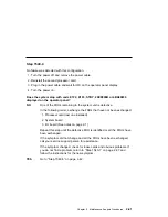
Go to “Step 1540-14” on page 2-51.
Chapter 2. Maintenance Analysis Procedures
2-49
Summary of Contents for H SERIES RS/6000
Page 1: ...RS 6000 Enterprise Server Model H Series IBM Installation and Service Guide SA38 0547 01...
Page 14: ...xiv RS 6000 Enterprise Server Model H Series Installation and Service Guide...
Page 34: ...1 18 RS 6000 Enterprise Server Model H Series Installation and Service Guide...
Page 106: ...2 72 RS 6000 Enterprise Server Model H Series Installation and Service Guide...
Page 178: ...3 72 RS 6000 Enterprise Server Model H Series Installation and Service Guide...
Page 262: ...7 14 RS 6000 Enterprise Server Model H Series Installation and Service Guide...
Page 279: ...Chapter 7 Removal and Replacement Procedures 7 31...
Page 315: ...Chapter 8 Parts Information Chapter 8 Parts Information 8 1...
Page 328: ...8 14 RS 6000 Enterprise Server Model H Series Installation and Service Guide...
Page 340: ...A 12 RS 6000 Enterprise Server Model H Series Installation and Service Guide...
Page 401: ...expect 8 r or 7 r or 6 r or 4 r or 3 r delay 2 done Appendix E Modem Configurations E 21...
Page 408: ...E 28 RS 6000 Enterprise Server Model H Series Installation and Service Guide...
Page 412: ...F 4 RS 6000 Enterprise Server Model H Series Installation and Service Guide...
Page 419: ...Index X 7...
Page 420: ...X 8 RS 6000 Enterprise Server Model H Series Installation and Service Guide...
Page 423: ......


