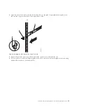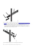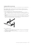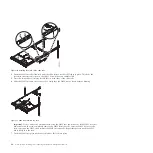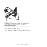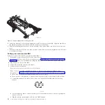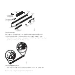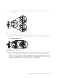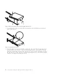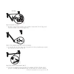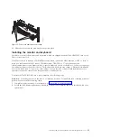
2.
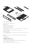
Ensure that you received all the parts that were ordered.
If there are incorrect, missing, or damaged parts, contact your IBM reseller or IBM sales and support.
Marking the location without using a rack-mounting template
You can mark the location without using a template.
A rack-mounting template is not included with this system. These systems are 1 EIA unit high.
To determine the mounting location, complete the following steps:
1.
Determine to place the system in the rack. Record the EIA location.
Note:
An EIA unit on your rack consists of a grouping of three holes.
2.
Facing the front of the rack and working from the right side, place a supplied self-adhesive dot next
to the top hole of the EIA unit.
Note:
The self-adhesive dots are used to aid in identifying locations on the rack. If you no longer
have any of the dots, use some other form of marking tool to aid you in identifying hole locations (for
example, tape, a marker, or pencil). If you are installing slide rails, place a mark or self-adhesive dot
on the lower and the middle hole of each EIA unit.
3.
Place another self-adhesive dot next to the bottom hole of the above EIA unit.
Note:
If you are counting the holes, begin with the hole identified by the first dot and count up two
holes. Place the second dot next to the third hole.
4.
Repeat step 1 on page 27 for the corresponding holes located on the left side of the rack.
5.
Go to the rear of the rack.
6.
On the right side, find the EIA unit that corresponds to the bottom EIA unit marked on the front of
the rack.
7.
Place a self-adhesive dot at the bottom EIA unit.
8.
Place a self-adhesive dot at the top hole of the EIA unit.
9.
Mark the corresponding holes on the left side of the rack.
Installing the monitor and keyboard into a rack
Learn how to install the monitor and keyboard that are shipped with the 7042-CR6 HMC into a rack.
The IBM 7316-TF3 17-inch, flat panel, rack-mounted, monitor and keyboard occupies 1.75 inches (1 EIA)
of rack-mounting space in a rack cabinet. You can use the brackets that are provided with this kit to
install an optional console switch in the same rack-mounting space as the monitor console kit.
To install the monitor and keyboard of the 7042-CR6 HMC into a rack, complete the following steps:
Attention:
Remove the rack doors and side panels to provide easy access for installation.
Complete the following steps to install the monitor and keyboard into a rack:
1.
Select a location in the rack for the monitor and keyboard tray. For more information, see Marking
the location.
2.
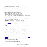
Install 4 cage nuts (on square-holed rack flanges) or 4 clip nuts (round-holed rack flanges) in the
same EIA positions on the front and rear of the rack.
Note:
If you plan to install the optional console switch, install a cage nut or clip nut in the
center-rear position as shown in the following illustration.
Installing and configuring the Hardware Management Console
43
Summary of Contents for Hardware Management Console
Page 1: ...Power Systems Installing and configuring the Hardware Management Console...
Page 2: ......
Page 3: ...Power Systems Installing and configuring the Hardware Management Console...
Page 8: ...vi Power Systems Installing and configuring the Hardware Management Console...
Page 107: ......
Page 108: ...Printed in USA...

