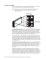
background image

Power-control


button:


This


button


is


located


behind


the


control


panel


door.


Press


this


button


to


manually


turn


the


blade


server


on


or


off.


Note:


This


button


has


effect


only


if


local


power


control


is


enabled


for


the


blade


server.


Local


power


control


is


enabled


and


disabled


through


the


BladeCenter


management


module


Web


interface.


Power-on


LED:


This


green


LED


indicates


the


power


status


of


the


blade


server


in


the


following


manner:


v


Flashing


rapidly


-


The


service


processor


on


the


blade


server


is


handshaking


with


the


BladeCenter


management


module.


v


Flashing


slowly


-


The


blade


server


has


power


but


is


not


turned


on.


v


Lit


continuously


-


The


blade


server


has


power


and


is


turned


on.

Activity


LED:


When


this


green


LED


is


lit,


it


indicates


that


there


is


hard


disk


drive


or


network


activity.


Location


LED:


When


this


blue


LED


is


lit,


it


has


been


turned


on


remotely


by


the


system


administrator


to


aid


in


visually


locating


the


blade


server.


The


location


LED


can


be


turned


off


through


the


BladeCenter


management-module


Web


interface


or


through


the


IBM


Director


Console.


v


Running


the


blade


server


integrated


diagnostics


v


Running


a


BIOS


update


diskette


on


a


blade


server


v


Updating


the


diagnostics


on


a


blade


server


If


there


is


no


response


when


you


press


the


keyboard/mouse/video


select


button,


you


can


use


the


management-module


Web


interface


to


see


whether


local


control


has


been


disabled


on


the


blade


server.


You


can


also


press


keyboard


keys


in


the


following


sequence


to


switch


keyboard/mouse/video


control


between


blade


servers:


NumLock


NumLock


blade


server


number


Enter


where


blade


server


number


is


the


two-digit


number


for


the


blade


bay


in


which


the


blade


server


is


installed.


A


blade


server


that


occupies


more


than


one


blade


bay


is


identified


by


the


lowest


bay


number


that


it


occupies.


If


you


install


the


Microsoft

®


Windows

®


2000


operating


system


on


the


blade


server


while


it


is


not


the


current


owner


of


the


keyboard,


video,


and


mouse,


a


delay


of


up


to


1


minute


occurs


the


first


time


you


switch


the


keyboard,


video,


and


mouse


to


the


blade


server.


During


this


one-time-only


delay,


the


blade


server


device


manager


enumerates


the


keyboard,


video,


and


mouse


and


loads


the


device


drivers.


All


subsequent


switching


takes


place


in


the


normal


keyboard-video-mouse


switching


time


frame


(up


to


20


seconds).


Information


LED:


When


this


LED


is


lit,


it


indicates


that


a


noncritical


event


has


occurred.


A


light


path


diagnostics


LED


on


the


processor


board


or


I/O


board


is


also


lit


to


help


isolate


the


error.


The


information


LED


can


be


turned


off


through


the


BladeCenter


management-module


Web


interface


or


through


the


IBM


Director


Console.


Blade-error


LED:


When


this


amber


LED


is


lit,


it


indicates


that


a


system


error


has


occurred


in


the


blade


server.


The


blade-error


LED


will


turn


off


only


after


the


error


is


corrected.


Chapter


1.


Introduction


9

Summary of Contents for HS40 - BladeCenter - 8839

Page 1: ...BladeCenter HS40 Type 8839 Hardware Maintenance Manual and Troubleshooting Guide ERserver...

Page 2: ......

Page 3: ...BladeCenter HS40 Type 8839 Hardware Maintenance Manual and Troubleshooting Guide ERserver...

Page 4: ...9 Fourth Edition May 2004 Note The most recent version of this document is available at http www ibm com pc support Copyright International Business Machines Corporation 2004 All rights reserved US Go...

Page 5: ...ger avant de proc der aux op rations d crites par les instructions Lesen Sie alle Sicherheitshinweise bevor Sie eine Anweisung ausf hren Accertarsi di leggere tutti gli avvisi di attenzione e di peric...

Page 6: ...iv BladeCenter HS40 Type 8839 Hardware Maintenance Manual and Troubleshooting Guide...

Page 7: ...ating system installation 15 Installing your operating system without ServerGuide 16 Using the PXE boot agent utility program 16 Firmware updates 17 Configuring the Gigabit Ethernet controllers 17 Bla...

Page 8: ...ling the blade server in the BladeCenter unit 65 Updating your blade server configuration 67 Input output connectors and devices 68 Chapter 5 Service replaceable units 69 Microprocessor removal 69 The...

Page 9: ...tices 149 Edition notice 149 Trademarks 150 Important notes 150 Product recycling and disposal 151 Battery return program 151 Electronic emission notices 152 Federal Communications Commission FCC stat...

Page 10: ...viii BladeCenter HS40 Type 8839 Hardware Maintenance Manual and Troubleshooting Guide...

Page 11: ...ur blade server are provided in Portable Document Format PDF on the IBM BladeCenter Documentation CD The machine type model number and serial number are on the ID label that is behind the control pane...

Page 12: ...illustration shows the placement of the label just to the side of the blade server on the BladeCenter T unit User label CMM 1 CMM 2 CD CD CD Related publications This Hardware Maintenance Manual and...

Page 13: ...BladeCenter problems yourself and information for service technicians v Eserver BladeCenter Type 8677 Rack Installation Instructions This publication contains instructions for installing the BladeCen...

Page 14: ...cm 2 32 inches v Maximum weight 7 0 kg 15 4 lb Integrated functions v Four Gigabit Ethernet controllers v ATI Radeon 7000 video controller v Light path diagnostics v Local service processor v IDE hard...

Page 15: ...ted Baseboard Management Controller v Universal Serial Bus USB v1 1 for communication with keyboard mouse diskette drive and CD ROM drive2 v Serial over LAN SOL management interface Electrical input I...

Page 16: ...the power features how to turn on and turn off the blade server and what the controls and indicators mean Turning on the blade server After you connect the blade server to power through the BladeCent...

Page 17: ...erating system documentation for information about shutting down the operating system Improper shutdown of a blade server will prevent that blade server from being restarted using Wake on LAN The blad...

Page 18: ...OM drive diskette drive and USB port The BladeCenter unit uses USB for internal communication with these devices If there is no response when you press the CD diskette USB select button you can use th...

Page 19: ...nt module Web interface to see whether local control has been disabled on the blade server You can also press keyboard keys in the following sequence to switch keyboard mouse video control between bla...

Page 20: ...10 BladeCenter HS40 Type 8839 Hardware Maintenance Manual and Troubleshooting Guide...

Page 21: ...on page 16 v IBM Remote Deployment Manager RDM Version 4 11 Update 3 or later IBM Remote Deployment Manager RDM is available for purchase You can use the IBM RDM Version 4 11 Update 3 or later to ins...

Page 22: ...Ethernet controller If you disable a device it cannot be configured and the operating system will not be able to detect it this is equivalent to disconnecting the device If you disable the Ethernet co...

Page 23: ...t be installed in the blade server that adhere to the special requirements described in Installing memory modules on page 44 CPU Options Select this choice to enable or disable hyper threading and adj...

Page 24: ...server is turned on Move the switch back to the previous position after the password is changed See Switches and jumpers on page 38 for the location of switch block 2 Using the ServerGuide Setup and...

Page 25: ...installation for supported Windows operating systems v Includes an online readme file with links to tips for your hardware and operating system installation Setup and configuration overview When you u...

Page 26: ...omplete the following steps to download the latest operating system installation instructions from the IBM Support Web page 1 Go to http www ibm com pc support 2 In the Download section click Download...

Page 27: ...and access to critical server settings v Around the clock access to the blade server even if the server is turned off At some time you might need to flash the service processor to apply the latest fi...

Page 28: ...the primary link fails a secondary controller takes over When the primary link is restored the Ethernet traffic switches back to the primary Ethernet controller See your operating system device driver...

Page 29: ...ace provides direct access to BladeCenter management functions as an alternative to using the management module Web interface Using the command line interface you can issue commands to control the pow...

Page 30: ...20 BladeCenter HS40 Type 8839 Hardware Maintenance Manual and Troubleshooting Guide...

Page 31: ...stics programs are stored in the upgradeable read only memory ROM IBM Director provides a real time diagnostics program that tests the major components of the blade server while the server operating s...

Page 32: ...ll suspect a problem see Undetermined problems on page 101 Diagnostic tools overview The following tools are available to help you diagnose and solve hardware related problems v Beep codes and error m...

Page 33: ...cause of the first error message the other error messages usually will not occur the next time you run the test Viewing the System Event Log SEL The System Setup Utility SSU is used to view the System...

Page 34: ...entries from a previously stored file v Save the SEL entries to a file v Clear the SEL entries from the non volatile storage area 24 BladeCenter HS40 Type 8839 Hardware Maintenance Manual and Troubles...

Page 35: ...Window displays information about a help topic Running the SEL Viewer You can run the SSU SEL Viewer from the Resource CD that comes with the blade server The latest SSU utility image can be download...

Page 36: ...rom which you can select different categories To exit from the help information press Esc Complete the following steps to start the diagnostic programs 1 Turn on the blade server and watch the screen...

Page 37: ...urself this function does not work with preformatted diskettes If the diskette has sufficient space for the test log the diskette may contain other data Diagnostic error message tables For description...

Page 38: ...DS6E1 DIMM 5 error LED DS6F1 DIMM 6 error LED DS6G1 DIMM 7 error LED DS6G2 DIMM 8 error LED DS6H1 Microprocessor 2 error LED DS5H4 Microprocessor 1 error LED DS5H5 Microprocessor 3 error LED DS5H1 Mic...

Page 39: ...e blade server on a flat non conductive surface 3 Remove the cover from the blade server 4 Press and hold the light path diagnostics button to relight the LEDs that were lit before you removed the bla...

Page 40: ...store the BIOS code to the primary page To recover the BIOS code complete the following steps 1 Turn off the blade server and remove the blade server from the BladeCenter unit see Removing the blade s...

Page 41: ...de server in the BladeCenter unit then restart the blade server The blade server starts Statement 21 CAUTION Hazardous energy is present when the blade server is connected to the power source Always r...

Page 42: ...32 BladeCenter HS40 Type 8839 Hardware Maintenance Manual and Troubleshooting Guide...

Page 43: ...ts See the instructions for removing or installing a specific hot swap component for any additional procedures that you might have to perform before you remove or install the component v For a list of...

Page 44: ...vice on your blade server cover or on a metal table v Take additional care when handling devices during cold weather Heating reduces indoor humidity and increases static electricity Major components o...

Page 45: ...socket 7 J9G1 DIMM socket 6 J9F1 DIMM socket 5 J9E2 DIMM socket 4 J9E1 DIMM socket 3 J9D1 DIMM socket 2 J9C2 DIMM socket 1 J9B3 DIMM 1 DIMM 2 DIMM 3 DIMM 4 DIMM 5 DIMM 6 DIMM 7 DIMM 8 I O board compo...

Page 46: ...on the processor board Microprocessor mismatch error LED DS5H3 Light path diagnostics button SW9J1 Light path diagnostics LED green DS9J1 DIMM 1 error LED DS6C1 DIMM 2 error LED DS6D1 DIMM 3 error LED...

Page 47: ...ary IDE error LED DS2H1 Secondary IDE error LED DS6H1 Processor board error LED DS8A2 Board error DS7A2 Light path diagnostics button S8A1 NMI error LED DS7A3 Temperature error LED DS7A4 I O board err...

Page 48: ...f Reserved Jumpers When the BIOS code page jumper J1E2 is moved from pins 1 and 2 to pins 2 and 3 you can start the blade server from a backup BIOS page The default position is pins 1 and 2 See the bl...

Page 49: ...em cooling do not operate the BladeCenter unit without either a blade server expansion unit or filler blade installed in each blade bay for more than 1 minute for the BladeCenter unit and 20 minutes f...

Page 50: ...ezel up and away from the BladeCenter T unit Carefully set the bezel assembly aside in a safe place 3 Pull the blade server out of the bay Spring loaded doors further back in the bay move into place t...

Page 51: ...n as shown in the illustration 4 Lay the cover flat or lift it from the blade server Statement 21 CAUTION Hazardous energy is present when the blade server is connected to the power source Always repl...

Page 52: ...and lift it off the blade server 3 Press the bezel assembly release and rotate the bezel assembly away from the blade server chassis then unhook the tabs on the bottom of the bezel from the holes on t...

Page 53: ...n configuring or replacing drives in a mirrored configuration IDE drive Riser card Tray Complete the following steps to install a 2 5 inch IDE drive Note Do not install an IDE drive into IDE connector...

Page 54: ...u must consider when installing DIMMs v The processor board contains eight DIMM connectors and supports two way memory interleaving v The DIMM options supported for your blade server are 256 MB 512 MB...

Page 55: ...g the blade server from the BladeCenter unit on page 39 for instructions 3 Carefully lay the blade server on a flat nonconductive surface 4 Open the blade server cover see Opening the blade server cov...

Page 56: ...rtain operating systems and application programs can distribute the processing load between the microprocessors To use SMP obtain an SMP capable operating system For a list of supported operating syst...

Page 57: ...ing the microprocessors 6 Locate the microprocessor socket on the processor board See Processor board components on page 35 for numbering order of processors Note Processors must be installed in order...

Page 58: ...fully open or Lever closed Lever fully open d Center the microprocessor over the microprocessor socket Align the triangle on the corner of the microprocessor with the triangle on the corner of the so...

Page 59: ...mpleting the installation on page 62 Installing an I O expansion card You can add one or two optional I O expansion cards to your blade server to give the blade server up to four additional network co...

Page 60: ...server from the BladeCenter unit on page 39 for information 3 Carefully lay the blade server on a flat nonconductive surface 4 Open the blade server cover see Opening the blade server cover on page 40...

Page 61: ...The following illustration shows how to install a PCI I O Expansion Unit on a blade server Air baffle Cover pins PCI I O Expansion Unit option Blade expansion connector terminator For complete inform...

Page 62: ...er unit Attention To ensure proper cooling and system reliability make sure that each of the SCSI hard disk drive bays on the SCSI storage expansion unit contains either a hot swap SCSI hard disk driv...

Page 63: ...the blade expansion connector on the processor board and remove the terminator from the connector Blade expansion connector terminator 6 Before installing the SCSI storage expansion unit check that al...

Page 64: ...d pushed down so that both heat sink captive mounting screws are through the holes in the air baffle Air baffle Microprocessor 1 and 4 heat sink captive mounting screws 8 Install the SCSI storage expa...

Page 65: ...No shield Shield Use SCSI storage expansion unit with no shield Do not use SCSI storage expansion with shield a Orient the storage expansion unit as shown in the illustration Cover pins Blade cover r...

Page 66: ...nto three adjacent BladeCenter unit bays Note When any blade server or option is in blade bay 7 through 14 in the BladeCenter unit or blade bay 5 through 8 in the BladeCenter T unit power modules must...

Page 67: ...wever this SCSI ID is changeable through the ServeRAID configuration program or the LSI configuration utility program Use the Configuration Setup Utility program in the blade server to enable or disab...

Page 68: ...ge 33 2 Remove the filler panel from one of the empty hot swap bays by inserting your finger into the depression at the top of the filler panel and pulling it away from the expansion unit 3 Install th...

Page 69: ...ety information beginning on page 109 and Installation guidelines on page 33 2 Locate the defective hard disk drive look for an amber status LED on the front of the hard disk drive 3 Make sure that th...

Page 70: ...ing a lithium battery replace it only with the same module type made by the same manufacturer The battery contains lithium and can explode if not properly used handled or disposed of Do not v Throw or...

Page 71: ...e battery out from under the battery clip 7 Insert the new battery a Tilt the battery so that you can insert it into the socket under the battery clip b As you slide it under the battery clip press th...

Page 72: ...lade server into the BladeCenter unit see Installing the blade server in the BladeCenter unit on page 65 4 Turn on the blade server see Turning on the blade server on page 6 Note Reinstall the bezel a...

Page 73: ...n the bottom of the bezel up into the matching holes on the server chassis then rotate the top of the bezel toward the server until the tabs at the top of the bezel snap into place Closing the blade s...

Page 74: ...nside the blade server Attention To help ensure proper cooling and system reliability the air baffle must be correctly positioned and fully seated 4 Make sure that the air baffle covering microprocess...

Page 75: ...the blade server Attention If you reinstall a blade that you removed you must install it in the same bays from which you removed it Some blade server configuration information and update options are e...

Page 76: ...e server are in the open position perpendicular to the blade 5 Slide the blade server into the bay until it stops The spring loaded doors further back in the bay that cover the bay opening move out of...

Page 77: ...e blade server Configuration Setup Utility and install the blade server operating system See Updating your blade server configuration and the IBM Eserver BladeCenter HS40 Type 8839 Installation and Us...

Page 78: ...s The blade server has two selection buttons on the control panel the CD diskette USB select button and the keyboard mouse video select button See Controls and LEDs on page 8 for information about the...

Page 79: ...e 112 Complete the following steps to remove a microprocessor 1 Shut down the operating system turn off the blade server and remove the blade server from the BladeCenter unit see Removing the blade se...

Page 80: ...position approximately 135 angle as shown Attention You must make sure that the locking lever on the microprocessor socket is in the fully open position before you remove the microprocessor from the...

Page 81: ...roprocessor see Installing an additional microprocessor on page 46 for instructions Attention If you are not installing a replacement microprocessor in socket 2 you must reinstall the microprocessor b...

Page 82: ...that all of the thermal grease is removed 4 Use a clean area of the cleaning pad to wipe the thermal grease from the microprocessor then dispose of the cleaning pad after all of the thermal grease is...

Page 83: ...SCSI storage expansion unit on page 51 5 Pivot the I O board tray to the upward position 6 Remove all components see the appropriate installation instructions and reverse the steps and place them on...

Page 84: ...ing on page 109 v Read Handling electrostatic discharge sensitive devices on page 112 Complete the following steps to remove the I O board 1 Shut down the operating system and turn off the blade serve...

Page 85: ...hat secure the I O board to the blade chassis and put the screws in a safe place 8 Pull the I O board carefully out of the blade chassis Reverse these steps to install the replacement I O board Chapte...

Page 86: ...76 BladeCenter HS40 Type 8839 Hardware Maintenance Manual and Troubleshooting Guide...

Page 87: ...in the list of the right column then restart the server to see if the problem has been corrected before taking further action Note Reseat a suspected component or reconnect a cable before replacing t...

Page 88: ...population rules violation microprocessor mismatch 1 Make sure all microprocessors are supported by the BIOS and of the same family model stepping speed and cache size 2 Microprocessor 1 5 4 2 Power f...

Page 89: ...s 2 Battery 3 I O board 0005 CMOS checksum bad loading defaults Information only no action required 0012 CMOS date time not set Run the Configuration Setup Utility program and set the date and time 00...

Page 90: ...3 thermal trip error 1 Check cooling 2 Replace blowers if needed 3 Run the Configuration Setup Utility program and enable the processor retest 4 Microprocessor 3 8123 Microprocessor 4 thermal trip err...

Page 91: ...l microprocessors are the same stepping speed family and cache size 3 Update BIOS to current level 8192 L2 Cache size mismatch 1 Microproocessor 2 Make sure all processors are the same stepping speed...

Page 92: ...RC error 1 DIMM 2 Processor board The following errors appear on the screen during POST and in the management module error log Note See Chapter 7 Parts listing Type 8839 on page 105 to determine which...

Page 93: ...X 000 Failed video test Processor board 030 XXX 000 Failed internal SCSI interface test 1 SCSI storage expansion unit 2 System board 035 XXX 099 1 No adapters were found 2 If adapter is installed re c...

Page 94: ...iled I2C bus error s See SERVPROC and DIAGS entries in event log 1 DIMMs 2 System board 166 201 002 System Management Failed I2C bus error s See SERVPROC and DIAGS entries in event log 1 Reseat I2C ca...

Page 95: ...ed diagnostics LED panel test System board 180 XXX 003 Failed system board LED test System board 180 XXX 005 Failed SCSI backplane LED test 1 SCSI storage expansion unit 2 System board 201 XXX 0nn Fai...

Page 96: ...stics LED Check the system error log for more information about the error DIMM error A memory error occurred 1 Reseat the DIMM indicated by the lit DIMM failure LED 2 Replace the DIMM Note Multiple DI...

Page 97: ...Replace the I O board NMI error A non maskable interrupt has occurred 1 Replace the blade server cover reinsert the blade server in the BladeCenter unit and then restart the blade server 2 Check the s...

Page 98: ...e etc fstab file dev cdrom media cdrom auto ro noauto user exec 0 0 CD ROM drive is not recognized after being switched back to blade server running Windows 2000 Advanced Server with SP3 applied When...

Page 99: ...d service technician Expansion enclosure problems Symptom FRU action The SCSI storage expansion unit used to work but does not work now 1 Make sure that the enclosure is installed correctly 2 For more...

Page 100: ...t button LED on the front of the blade server is lit indicating that the blade server is connected to the shared BladeCenter monitor v The mouse or pointing device cable is securely connected to the B...

Page 101: ...89 v If the DIMM was disabled by a system management interrupt SMI replace the DIMM v If the DIMM was disabled by the user or by POST a Start the Configuration Setup Utility program b Enable the DIMM...

Page 102: ...etup Utility program is set to Enabled its default setting you must restart the computer three times to force the system BIOS to reset the CMOS values to the default configuration memory connector or...

Page 103: ...the correct language in the blade server that has ownership of the monitor 2 Monitor 3 System board No video 1 Make sure the correct machine is selected if applicable 2 Make sure all cables are locked...

Page 104: ...t blade bay supports 3 Try another blade server in the blade bay if it works replace the faulty blade server 4 See Undetermined problems on page 101 The blade server does not turn on and the following...

Page 105: ...operating system is supported either there is no logical drive defined SCSI RAID systems or the ServerGuide System Partition is not present Run the ServerGuide program and make sure that setup is com...

Page 106: ...Service processor problems Symptom FRU action Service processor in the management module reports a general monitor failure Disconnect the BladeCenter unit from all electrical sources wait for 30 secon...

Page 107: ...Expansion option CPU x over temperature 1 Ensure that the system is being properly cooled see System reliability considerations on page 33 2 Replace microprocessor x Power error messages Note See Cha...

Page 108: ...deCenter Type 8677 Hardware Maintenance Manual and Troubleshooting Guide 2 Reseat blade storage expansion option 3 Replace blade storage expansion option BSE 2 5V over recommended voltage 1 Check Blad...

Page 109: ...heck BladeCenter power see IBM BladeCenter Type 8677 Hardware Maintenance Manual and Troubleshooting Guide 2 Reseat blade server 3 Replace blade server System over recommended voltage for 3 3v 1 Check...

Page 110: ...roubleshooting Guide 2 Reseat blade server 3 Replace blade server System under recommended 5V fault 1 Check BladeCenter power see IBM BladeCenter Type 8677 Hardware Maintenance Manual and Troubleshoot...

Page 111: ...down See IBM BladeCenter Type 8677 Hardware Maintenance Manual and Troubleshooting Guide Hard disk drive checkout Note See Chapter 7 Parts listing Type 8839 on page 105 to determine which components...

Page 112: ...s minimum requirement two 256 MB DIMMs The following components are required at a minimum for the blade server to operate v System board v One microprocessor v Memory with a minimum of two 256 MB DIMM...

Page 113: ...if they v Are the exact machine type and model v Have the same BIOS code level v Have the same adapters and attachments in the same locations v Have the same address jumpers terminators and cabling v...

Page 114: ...104 BladeCenter HS40 Type 8839 Hardware Maintenance Manual and Troubleshooting Guide...

Page 115: ...Memory module 512 MB PC2100 ECC 21X 51X 61X 71X 6TX 09N4307 CRU 3 Memory module 1 GB PC2100 ECC 31X 41X 61X 71X 61X 09N4308 CRU 3 Memory module 2GB PC2100 ECC all models 09N4309 FRU 4 Processor board...

Page 116: ...bre channel adapter tray optional 49P2514 CRU Fibre channel card optional 59P6624 CRU Gigabit Ethernet daughter card 13N2306 CRU System service label 25K9830 CRU Warning label all models 90P4799 FRU M...

Page 117: ...ce by following the troubleshooting procedures that IBM provides in the online help or in the publications that are provided with your system and software The information that comes with your system a...

Page 118: ...s are supported by Support Line in your country or region go to http www ibm com services sl products For more information about Support Line and other IBM services go to http www ibm com services or...

Page 119: ...s to the customer or that makes the equipment unsafe v Before you start the machine ensure that other service representatives and the customer s personnel are not in a hazardous position v Place remov...

Page 120: ...ion Working near power supplies Removing or installing main units v Before you start to work on the machine unplug the power cord If you cannot unplug it ask the customer to power off the wall box tha...

Page 121: ...itions on these products Each machine as it was designed and built had required safety items installed to protect users and service personnel from injury This guide addresses only those items However...

Page 122: ...en handling ESD sensitive parts v Keep the parts in protective packages until they are inserted into the product v Avoid contact with other people v Wear a grounded wrist strap against your skin to el...

Page 123: ...stallation maintenance or reconfiguration of this product during an electrical storm v Connect all power cords to a properly wired and grounded electrical outlet v Connect to properly wired outlets an...

Page 124: ...hen laser products such as CD ROMs DVD ROM drives fiber optic devices or transmitters are installed note the following v Do not remove the covers Removing the covers of the laser product could result...

Page 125: ...device The device also might have more than one power cord To remove all electrical current from the device ensure that all power cords are disconnected from the power source 1 2 Statement 10 CAUTION...

Page 126: ...rgy is present when the blade server is connected to the power source Always replace the blade cover before installing the blade server 116 BladeCenter HS40 Type 8839 Hardware Maintenance Manual and T...

Page 127: ...e aterradas v Conecte todos os equipamentos ao qual esse produto ser conectado a tomadas corretamente instaladas v Sempre que poss vel utilize apenas uma das m os para conectar ou desconectar cabos de...

Page 128: ...rreio para a IBM Instru o 3 PRECAUCI N Quando produtos a laser unidades de CD ROM unidades de DVD dispositivos de fibra tica transmissores etc estiverem instalados observe o seguinte v N o remova as t...

Page 129: ...itivo tamb m pode ter mais de um cabo de alimenta o Para remover toda a corrente el trica do dispositivo assegure que todos os cabos de alimenta o estejam desconectados da fonte de energia el trica 1...

Page 130: ...ergia uma amea a quando a l mina estiver conectada fonte de alimenta o Sempre substitua a cobertura da l mina antes de efetuar a instala o 120 BladeCenter HS40 Type 8839 Hardware Maintenance Manual an...

Page 131: ...Appendix B Safety information 121...

Page 132: ...122 BladeCenter HS40 Type 8839 Hardware Maintenance Manual and Troubleshooting Guide...

Page 133: ...Appendix B Safety information 123...

Page 134: ...124 BladeCenter HS40 Type 8839 Hardware Maintenance Manual and Troubleshooting Guide...

Page 135: ...Appendix B Safety information 125...

Page 136: ...126 BladeCenter HS40 Type 8839 Hardware Maintenance Manual and Troubleshooting Guide...

Page 137: ...Appendix B Safety information 127...

Page 138: ...ect ce produit v Lorsque cela est possible n utilisez qu une seule main pour connecter ou d connecter les c bles d interface v Ne mettez jamais un quipement sous tension en cas d incendie ou d inondat...

Page 139: ...ION Si des produits laser sont install s tels que des unit s de CD ROM ou de DVD des p riph riques contenant des fibres optiques ou des metteurs r cepteurs prenez connaissance des informations suivant...

Page 140: ...e Il se peut que votre unit dispose de plusieurs cordons d alimentation Pour isoler totalement l unit du r seau lectrique d branchez tous les cordons d alimentation des socles de prise de courant 1 2...

Page 141: ...courant lectrique dangereux est pr sent lorsque le Serveur lame est connect une source d alimentation Remettez toujours en place le carter du Serveur lame avant d installer le Serveur lame Appendix B...

Page 142: ...sgem geerdetem Schutzkontakt anschlie en v Signalkabel m glichst einh ndig anschlie en oder l sen v Keine Ger te einschalten wenn die Gefahr einer Besch digung durch Feuer Wasser oder andere Einfl sse...

Page 143: ...werke Einheiten mit Glasfaserkabeln oder Transmitter installiert ist beachten Sie folgendes v Das Entfernen der Abdeckungen des CD ROM Laufwerks kann zu gef hrlicher Laserstrahlung f hren Es befinden...

Page 144: ...Server k nnte auch mehr als ein Netzkabel aufweisen Um die gesamte Stromversorgung des Servers auszuschalten mu sichergestellt werden da alle Netzkabel aus den Netzsteckdosen herausgezogen wurden 1 2...

Page 145: ...21 ACHTUNG Wenn das Blade an eine Stromquelle angeschlossen ist besteht die Gefahr eines Stromschlags Bringen Sie die Abdeckung der Blades immer an bevor Sie sie installieren Appendix B Safety informa...

Page 146: ...ura collegata a questo prodotto ad una presa elettrica correttamente cablata e munita di terra di sicurezza v Quando possibile collegare o scollegare i cavi di segnale con una sola mano v Non accender...

Page 147: ...sposizioni nazionali e locali Avviso 3 ATTENZIONE Quando si installano prodotti laser come ad esempio le unit DVD CD ROM a fibre ottiche o trasmettitori prestare attenzione a quanto segue v Non rimuov...

Page 148: ...one siano scollegati dalla sorgente di alimentazione 1 2 Avviso 10 ATTENZIONE Non poggiare oggetti che pesano pi di 82 kg sulla parte superiore delle unit montate in rack Avviso 20 ATTENZIONE Per evit...

Page 149: ...Appendix B Safety information 139...

Page 150: ...140 BladeCenter HS40 Type 8839 Hardware Maintenance Manual and Troubleshooting Guide...

Page 151: ...Appendix B Safety information 141...

Page 152: ...142 BladeCenter HS40 Type 8839 Hardware Maintenance Manual and Troubleshooting Guide...

Page 153: ...Appendix B Safety information 143...

Page 154: ...144 BladeCenter HS40 Type 8839 Hardware Maintenance Manual and Troubleshooting Guide...

Page 155: ...tomas de alimentaci n con un cableado correcto cualquier equipo que vaya a estar conectado a este producto v Si es posible utilice una sola mano cuando conecte o desconecte los cables de sent al v No...

Page 156: ...cal Declaraci n 3 PRECAUCI N Cuando instale productos l ser como por ejemplo CD ROM unidades DVD dispositivos de fibra ptica o transmisores tenga en cuenta las advertencias siguientes v No retire las...

Page 157: ...mbi n que el dispositivo tenga m s de un cable de alimentaci n Para eliminar la corriente el ctrica del dispositivo aseg rese de desconectar todos los cables de alimentaci n de la fuente de alimentaci...

Page 158: ...N Existe energia perigosa quando a l mina est ligada fonte de alimenta o Substitua sempre a cobertura da l mina antes de instalar a mesma 148 BladeCenter HS40 Type 8839 Hardware Maintenance Manual an...

Page 159: ...TY OF ANY KIND EITHER EXPRESS OR IMPLIED INCLUDING BUT NOT LIMITED TO THE IMPLIED WARRANTIES OF NON INFRINGEMENT MERCHANTABILITY OR FITNESS FOR A PARTICULAR PURPOSE Some states do not allow disclaimer...

Page 160: ...or both UNIX is a registered trademark of The Open Group in the United States and other countries Java and all Java based trademarks and logos are trademarks or registered trademarks of Sun Microsyst...

Page 161: ...recycling and disposal This unit contains materials such as circuit boards cables electromagnetic compatibility gaskets and connectors which may contain lead and copper beryllium alloys that require...

Page 162: ...ed changes or modifications to this equipment Unauthorized changes or modifications could void the user s authority to operate the equipment This device complies with Part 15 of the FCC Rules Operatio...

Page 163: ...s been tested and found to comply with the limits for Class A Information Technology Equipment according to CISPR 22 European Standard EN 55022 The limits for Class A equipment were derived for commer...

Page 164: ...in these countries and regions 02K0546 China 13F9940 Australia Fiji Kiribati Nauru New Zealand Papua New Guinea 13F9979 Afghanistan Albania Algeria Andorra Angola Armenia Austria Azerbaijan Belarus B...

Page 165: ...Barbados Belize Bermuda Bolivia Brazil Caicos Islands Canada Cayman Islands Costa Rica Colombia Cuba Dominican Republic Ecuador El Salvador Guam Guatemala Haiti Honduras Jamaica Japan Mexico Micronesi...

Page 166: ...156 BladeCenter HS40 Type 8839 Hardware Maintenance Manual and Troubleshooting Guide...

Page 167: ...ut 68 memory 35 microprocessor 35 processor board 35 controller enable or disable Ethernet 12 Ethernet 17 SCSI 52 57 controller enumeration 18 cover closing 63 removing 40 D diagnostic error codes 83...

Page 168: ...d problems 90 L LEDs activity 9 blade system error 9 LEDs continued control panel 8 I O board 27 36 information 9 location 9 power on 9 processor board 27 35 36 light path diagnostics 86 light path di...

Page 169: ...placing battery 59 I O board 74 replacing continued microprocessor 69 processor board 72 S SCSI IDs 57 SCSI errors 97 SCSI storage expansion unit device drivers 56 enable or disable 57 serial over LAN...

Page 170: ...lass A notice 152 Universal Serial Bus USB problems 95 updating firmware 17 utility Configuration Setup Utility program 11 PXE boot agent program using 16 W Web site ServerGuide 14 supported blade ser...

Page 171: ......

Page 172: ...Part Number 25K8105 Printed in USA 1P P N 25K8105...

Reviews: