background image

Trademarks


The


following


terms


are


trademarks


of


International


Business


Machines


Corporation


in


the


United


States,


other


countries,


or


both:


Active


Memory


Predictive


Failure


Analysis


Active


PCI


PS/2


Active


PCI-X


ServeRAID


Alert


on


LAN


ServerGuide


BladeCenter


ServerProven


C2T


Interconnect


TechConnect


Chipkill


ThinkPad


EtherJet


Tivoli


e-business


logo


Tivoli


Enterprise


Eserver


Update


Connector


FlashCopy


Wake


on


LAN


IBM


XA-32


IBM


(logo)


XA-64


IntelliStation


X-Architecture


NetBAY


XceL4


Netfinity


XpandOnDemand


NetView


xSeries


OS/2


WARP


Intel,


MMX,


and


Pentium


are


trademarks


of


Intel


Corporation


in


the


United


States,


other


countries,


or


both.


Microsoft,


Windows,


and


Windows


NT


are


trademarks


of


Microsoft


Corporation


in


the


United


States,


other


countries,


or


both.


UNIX


is


a


registered


trademark


of


The


Open


Group


in


the


United


States


and


other


countries.


Java


and


all


Java-based


trademarks


and


logos


are


trademarks


or


registered


trademarks


of


Sun


Microsystems,


Inc.


in


the


United


States,


other


countries,


or


both.


Adaptec


and


HostRAID


are


trademarks


of


Adaptec,


Inc.,


in


the


United


States,


other


countries,


or


both.


Red


Hat,


the


Red


Hat


“Shadow


Man”


logo,


and


all


Red


Hat-based


trademarks


and


logos


are


trademarks


or


registered


trademarks


of


Red


Hat,


Inc.,


in


the


United


States


and


other


countries.


Other


company,


product,


or


service


names


may


be


trademarks


or


service


marks


of


others.


Important


notes


Processor


speeds


indicate


the


internal


clock


speed


of


the


microprocessor;


other


factors


also


affect


application


performance.


CD-ROM


drive


speeds


list


the


variable


read


rate.


Actual


speeds


vary


and


are


often


less


than


the


maximum


possible.


104


IntelliStation


A


Pro


Type


6224:


User’s


Guide

Summary of Contents for IntelliStation A Pro 6224

Page 1: ...IntelliStation A Pro Type 6224 User s Guide...

Page 2: ......

Page 3: ...IntelliStation A Pro Type 6224 User s Guide...

Page 4: ...x B Notices on page 103 and the Warranty information in the Installation Guide Second Edition June 2004 Copyright International Business Machines Corporation 2004 All rights reserved US Government Use...

Page 5: ...or settings 15 Using audio features 16 Using security features 16 Anti intrusion features 16 Component protection 16 Data protection 17 Locking the keyboard 17 Updating system programs 17 Managing you...

Page 6: ...Input output connectors 64 Audio connectors 65 Auxiliary device pointing device connector 66 Ethernet RJ 45 connector 66 IEEE 1394A FireWire connector 66 Keyboard connector 67 Parallel connector 67 Se...

Page 7: ...ring from a POST BIOS update failure 97 Erasing a lost or forgotten password clearing CMOS 98 Replacing the battery 99 Appendix A Getting help and technical assistance 101 Before you call 101 Using th...

Page 8: ...vi IntelliStation A Pro Type 6224 User s Guide...

Page 9: ...lleert eerst de veiligheidsvoorschriften Ennen kuin asennat t m n tuotteen lue turvaohjeet kohdasta Safety Information Avant d installer ce produit lisez les consignes de s curit Vor der Installation...

Page 10: ...disconnect signal cables v Never turn on any equipment when there is evidence of fire water or structural damage v Disconnect the attached power cords telecommunications systems networks and modems be...

Page 11: ...ces or regulations Statement 3 CAUTION When laser products such as CD ROMs DVD drives fiber optic devices or transmitters are installed note the following v Do not remove the covers Removing the cover...

Page 12: ...on on the device and the power switch on the power supply do not turn off the electrical current supplied to the device The device also might have more than one power cord To remove all electrical cur...

Page 13: ...you to lead a chemical known to the State of California to cause cancer and birth defects or other reproductive harm Wash hands after handling ADVERTENCIA El contacto con el cable de este producto o c...

Page 14: ...afety Information document under statement 1 Be sure to read all caution and danger statements in this documentation before performing the instructions Read any additional safety information that come...

Page 15: ...evice Drivers CD It contains information and instructions for installing and configuring small computer system interface SCSI device drivers and devices v Readme files on the Device Drivers CD Several...

Page 16: ...rtant tips guidance or advice v Important These notices provide information or advice that might help you avoid inconvenient or problem situations v Attention These notices indicate potential damage t...

Page 17: ...onous dynamic random access memory SDRAM video memory and dual analog connectors or dual digital monitor capability with the purchase of an additional pigtail cable v NVIDIA Quadro FX 1100 DVI I AGP 8...

Page 18: ...n LAN Remote Administration and IBM Director Agent See Managing your computer on page 18 for more information v Integrated network support Your computer comes with an integrated Ethernet controller wh...

Page 19: ...register your computer with IBM information is entered into a database so that you can be contacted in case of a recall or other problems Some locations offer extended privileges and services to regi...

Page 20: ...ation about your hardware and software set up alerts monitor a variety of system resources and manage your asset security IBM Director Agent streamlines and automates personal computer PC systems mana...

Page 21: ...v Built in menu driven configuration and setup programs v Built in menu driven SCSI configuration programs some models v Diagnostic programs v Cooling fans with speed sensing capability v Error codes...

Page 22: ...8 IntelliStation A Pro Type 6224 User s Guide...

Page 23: ...USB 4 connector Ethernet transmit receive activity LED CD ROM drive activity LED When this LED is lit it indicates that the CD ROM drive is in use CD eject button Press this button to insert a CD int...

Page 24: ...all core logic is shut down however the computer can respond to remote requests to turn on the computer The power on LED flashes to indicate that the computer is connected to an ac power source but is...

Page 25: ...PCI adapters and other options The operating system and application programs start from the hard disk If your computer is attached to a network the computer will begin attaching to any LANs and remote...

Page 26: ...m other than Microsoft Windows XP Professional or Red Hat Enterprise Linux Workstation follow the instructions in the readme files on the Device Drivers CD to install the device drivers You might also...

Page 27: ...ram click Devices and I O Ports Disable Legacy Diskette A At your earliest opportunity create a recovery repair diskette and an IBM Enhanced Diagnostics diskette and store them in a safe place In the...

Page 28: ...2 When the message To start the Product Recovery Program Press F11 appears quickly Press F11 3 Select System utilities 4 Select Create IBM Enhanced Diagnostics Diskette 5 Follow the instructions on t...

Page 29: ...ough the operating system using the instructions in the readme files on the Device Drivers CD or in the c ibmtools drivers directory on the hard disk See your operating system documentation for more i...

Page 30: ...ware Microphone connectors are on both the front and the rear of the computer Using security features To deter unauthorized use of your computer you can use anti intrusion features and other security...

Page 31: ...d disk Locking the keyboard You can lock the keyboard so that others are unable to use it If you have set a user password the keyboard is locked when you turn on the computer You must type the passwor...

Page 32: ...A network administrator can use the Wake on LAN feature to turn on your computer from a remote location When the Wake on LAN feature is used with network management software many functions such as dat...

Page 33: ...n about shutting down the operating system Statement 5 CAUTION The power control button on the device and the power switch on the power supply do not turn off the electrical current supplied to the de...

Page 34: ...ower control button for more than 4 seconds to cause an immediate shutdown of the computer You can use this feature to turn off the computer if the operating system stops functioning 20 IntelliStation...

Page 35: ...bout using these utility programs see Using the Adaptec RAID Configuration Utility programs for Serial ATA RAID on page 26 SCSISelect Utility program for SCSI RAID Use the SCSI HostRAID feature of SCS...

Page 36: ...enus v System Information Select this choice to view the machine type and model of the computer the serial number the system board identifier and the revision level and issue date of the BIOS code sto...

Page 37: ...e instructions on the screen carefully This choice is on the full Configuration Setup Utility menu only Installed OS Select this choice to specify the operating system on the computer Reset Configurat...

Page 38: ...aving them Note Always reset the Configuration Setup Utility program to the default values select Load Default Settings after updating the BIOS code Passwords From the System Security choice you can s...

Page 39: ...controller and the integrated SCSI controller Be sure to use these programs as described in this document Use these programs to v Configure a redundant array of independent disks RAID array v View or...

Page 40: ...croll down and select SATA RAID Enable 5 Select Enabled 6 Press Esc then select Yes to save your changes Using the Serial ATA HostRAID feature The instructions in this section are for using the Array...

Page 41: ...the message Press CTRL A for SCSISelect Utility appears press Ctrl A If you have set a supervisor password you are prompted to type the password 3 Use the arrow keys to select the channel for which y...

Page 42: ...o available from the Help menu For information about a specific object in the ServeRAID Manager tree select the object and click Actions Hints and tips Configuring the controller By running ServeRAID...

Page 43: ...he icon to add the drives to the array 7 Complete the following steps if you want to configure a hot spare drive a Click the Spares tab b Select the physical drive you want to designate as the hot spa...

Page 44: ...ress Ctrl A If you have set an administrator password you are prompted to type the password 3 Use the arrow keys to select a choice for which you want to change settings and press Enter 4 When the pro...

Page 45: ...on options v SCSI Disk Utilities Select this choice to view the SCSI IDs assignments or to format a SCSI device Select a device from the list and read the instructions on the screen carefully before m...

Page 46: ...32 IntelliStation A Pro Type 6224 User s Guide...

Page 47: ...sure proper cooling and system reliability make sure that v Each of the drive bays has a drive or a filler panel and electromagnetic compatibility EMC shield installed in it v There is adequate space...

Page 48: ...duces indoor humidity and increases static electricity Installing options in your computer This section provides instructions for installing hardware options in your computer Note To remove the side c...

Page 49: ...ustration shows the system board connectors for user installable options DIMM 1 DIMM 2 DIMM 3 DIMM 4 Battery PCI X 1 PCI X 2 PCI X 3 AGP PCI X 4 PCI X 5 Microprocessor board for microprocessor 2 Micro...

Page 50: ...SCSI channel B Extender board power Intrusion switch Speaker Front panel audio CD ROM audio in Rear system fan 2 Rear system fan 1 Reserved System error LED Optional microprocessor board connectors I...

Page 51: ...mplete the following steps to remove the side cover of the computer 1 Read the safety information beginning on page vii and the guidelines in Handling static sensitive devices on page 33 2 Turn off th...

Page 52: ...isk drives adapters and memory modules you must first remove the support bracket to access the device Complete the following steps to remove the support bracket 1 Read safety information beginning on...

Page 53: ...tical drives you must first remove the bezel to access the device Complete the following steps to remove the bezel 1 Unlock the side cover lock 2 Remove the side cover see Removing the side cover on p...

Page 54: ...mes with your operating system v Locate the documentation that comes with the adapter and follow those instructions in addition to the instructions in this chapter If you need to change the switch or...

Page 55: ...the instructions that come with the adapter for any requirements restrictions or cabling instructions It might be easier to route cables before you install the adapter 5 For full length adapters rotat...

Page 56: ...dapter bracket into the screw hole and secure the adapter before proceeding to the next step If you use a screw to secure an adapter you will have to secure all adapters with screws You cannot use bot...

Page 57: ...rmation that you must consider when cabling an optional SCSI adapter v The SCSI cables that are used by the integrated SCSI controller cannot be used with an optional SCSI adapter v If you install a S...

Page 58: ...ive in bay 3 or a USB drive connected to the USB connector on the front of the computer v If you plan to install a Microsoft Windows XP 32 bit operating system on a SCSI drive you must have a diskette...

Page 59: ...documentation that comes with your drive 2 Make sure that you have all the cables and other equipment that is specified in the documentation that comes with the drive 3 Check the instructions that com...

Page 60: ...in hazardous radiation exposure DANGER Some laser products contain an embedded Class 3A or Class 3B laser diode Note the following Laser radiation when open Do not stare into the beam do not view dir...

Page 61: ...internal drives on page 52 for additional information about cabling drives and System board internal connectors on page 36 for the location of IDE and SCSI connectors on the system board If there are...

Page 62: ...hether you need to set any switches or jumpers on the drive If you are installing a SCSI device make sure that you set the SCSI ID for that device 4 Turn off the computer and all attached devices then...

Page 63: ...t result in hazardous radiation exposure DANGER Some laser products contain an embedded Class 3A or Class 3B laser diode Note the following Laser radiation when open Do not stare into the beam do not...

Page 64: ...15 If you have other options to install or remove do so now 16 Replace the support bracket see Removing and installing the support bracket on page 38 17 Replace the bezel see Replacing the bezel on pa...

Page 65: ...bay slide the existing drive tray out of the drive bay If you are replacing a drive complete the following steps a Slide the existing drive out of the drive bay b Remove the drive from the drive tray...

Page 66: ...installing the support bracket on page 38 20 Replace the side cover see Replacing the side cover on page 63 21 Reconnect the external cables and power cords then turn on the attached devices and the...

Page 67: ...following cables can be used to attach SCSI devices to the integrated SCSI controller on the system board An Ultra320 twisted ribbon cable connects the internal Ultra320 SCSI hard disk drive to the S...

Page 68: ...MMs for the microprocessor in DIMM connectors 5 and 6 on the microprocessor option board If you install a second pair of DIMMs for the microprocessor install the pair in DIMM connectors 7 and 8 on the...

Page 69: ...of the computer 7 Locate the DIMM connectors Determine the connectors into which you will install the DIMMs See the notes on page 54 for the installation sequence 8 Gently open the retaining clips on...

Page 70: ...r in step 6 replace the air baffle 16 Replace the support bracket see Removing and installing the support bracket on page 38 17 Replace the side cover see Replacing the side cover on page 63 18 Reconn...

Page 71: ...processor to determine whether you need to update the computer basic input output system BIOS code The most current level of BIOS code for the computer is available from http www ibm com pc support v...

Page 72: ...stick straight down and align with the six screw holes on the system board c Make sure that the connectors on the underside of the microprocessor board line up with the second microprocessor connecto...

Page 73: ...from the package b Position the microprocessor over the microprocessor socket as shown in the following illustration Carefully press the microprocessor into the socket Attention To avoid bending the...

Page 74: ...e fan sink and the fan sink screws do not come in contact with any electrical components on the microprocessor board e Connect the fan sink cable to the microprocessor fan connector on the microproces...

Page 75: ...21 Reconnect the external cables and power cords Turn on the attached devices and turn on the computer Installing an external SCSI cable To install an external SCSI connector on the rear of the compu...

Page 76: ...embedded connector into the slot opening 8 Replace any adapters you removed in step 4 Close the front adapter retention bracket and replace the rear adapter retention bracket 9 Replace the support br...

Page 77: ...rver chassis 2 Push the top of the bezel toward the server until the two tabs at the top of the bezel snap into place Replacing the side cover If you removed the support bracket reinstall it before yo...

Page 78: ...devices on page 33 and the documentation that comes with your options 2 Turn off the computer and all attached devices see Turning off the computer on page 19 3 Follow the instructions that come with...

Page 79: ...onnector knockout The following sections describe these connectors Audio connectors Use the audio connectors to connect external audio equipment to the computer The following illustration shows the au...

Page 80: ...ws an Ethernet connector 1 8 Link LED green Activity LED green Connect a Category 3 4 or 5 unshielded twisted pair UTP cable to this connector The 100BASE TX and 1000BASE T Fast Ethernet standards req...

Page 81: ...you configure the parallel port to operate in bidirectional mode it supports the ECP and EPP modes When the parallel connector is configured as bidirectional use an IEEE 1284 compliant cable that doe...

Page 82: ...n the same SCSI channel do not attempt to transfer data simultaneously SCSI devices that are connected to different SCSI channels can have duplicate SCSI IDs See the information that comes with the de...

Page 83: ...ow force helical 60 LFH 60 video connector Stereo shutter glasses video connector StereoGraphics Some models come with a digital video interface DVI connector for connecting a digital monitor If you h...

Page 84: ...onnect the video adapter to the computer power supply This means that when you install this video adapter in your computer you have one less power drop for optional internal devices The following illu...

Page 85: ...ormation Additional information is recorded in the system error logs For detailed information see POST Error Log in Advanced Setup in Configuration Setup Utility menu choices on page 22 v Diagnostic p...

Page 86: ...cables for loose connections and verify that all optional devices you installed are on the compatibility matrix You can view the at compatibility matrix http www pc ibm com us compat intellistation C...

Page 87: ...odes Use the following beep code descriptions to help diagnose and solve problems that are detected during startup No beeps If no beep occurs after the computer completes POST call for service Continu...

Page 88: ...iled 3 2 3 Math coprocessor test has failed 3 2 4 Comparison of CMOS memory size against actual has failed 3 3 1 A memory size mismatch has occurred Reseat the memory modules or install a memory modul...

Page 89: ...the battery However you must run the Configuration Setup Utility program and set the time and date and other custom settings each time you turn on the computer 162 A change in device configuration occ...

Page 90: ...p Utility program select System Information and then select Product Data If the problem remains call for service 188 A vital product data VPD error occurred Action Start the Configuration Setup Utilit...

Page 91: ...drive test Action Take the following steps to correct the problem 1 Make sure that the Configuration Setup Utility program correctly reflects the type of diskette drive that you have installed 2 Run t...

Page 92: ...ause this error Note This error also can occur if electrical power was lost for a very brief period and then restored In this case turn off the computer for at least 5 seconds then turn it back on Act...

Page 93: ...on page 14 for instructions Note When using diagnostics with a USB keyboard and mouse attached you must first enable USB emulation Complete the following steps to enable USB emulation 1 Restart the c...

Page 94: ...he computer and when the message To start the Product Recovery program is displayed quickly press F11 b Select System utilities c Select Run diagnostics to start the diagnostics programs v To start th...

Page 95: ...y connected to the external serial port 2 Make sure that the cable from the external serial port is correctly connected to the system board 3 Call for service 014 Parallel port Integrated parallel por...

Page 96: ...in location DIMM n where n is the number of the socket that contains the failing DIMM 1 Reseat the failing DIMM 2 If the problem remains replace the DIMM If the problem remains call for service Test...

Page 97: ...onnected to the CD ROM drive 3 Run the test again 4 Call for service Aborted The CD ROM drive is not present Make sure that the cables are correctly connected to the CD ROM drive If the problem remain...

Page 98: ...e Note The push button test is applicable only to SCSI tape drives that have a push button The self diagnostic failed for device n on adapter m where n is the number of the device and m is the adapter...

Page 99: ...t 2 Replace the pointing device 3 Call for service 305 Video monitor Any message See the information that came with the monitor 405 Ethernet Failed In PCI X slot n where n is the PCI X slot number in...

Page 100: ...puter contains PC Doctor for Windows which is designed specifically for the Windows operating environment Because these diagnostics work with the operating system they test hardware and analyze certai...

Page 101: ...tray release opening If the problem remains call for service Diskette drive problems Symptom Suggested action The diskette drive activity LED stays lit or the computer bypasses the diskette drive v I...

Page 102: ...er is turned on air is flowing from the rear of the computer at the fan grille If there is no airflow the fans are not working This can cause the computer to overheat and shut down v The SCSI bus and...

Page 103: ...ssor is not working correctly Call for service Monitor problems Some IBM monitors have their own self tests If you suspect a problem with your monitor see the information that comes with the monitor f...

Page 104: ...en If the wrong language is displayed update the BIOS code with the correct language If the problem remains call for service Option problems Symptom Suggested action An IBM option that was just instal...

Page 105: ...mine whether you are using an ACPI or non ACPI operating system If you are using a non ACPI operating system complete the following steps 1 Press Ctrl Alt Delete 2 Turn off the computer by holding the...

Page 106: ...the computer does not have a memory address conflict The software is designed to operate on the computer Other software works on the computer The software that you are using works on another computer...

Page 107: ...sor it is installed on a microprocessor board which is installed on the system board The following illustration shows the error LEDs on the microprocessor board Each error LED is lit to indicate a pro...

Page 108: ...sk drive contact IBM to order the IBM Product Recovery CD to recover your preinstalled operating system application programs and device drivers See Appendix A Getting help and technical assistance on...

Page 109: ...rogram and the Device Drivers CD Before you can recover or install device drivers your operating system must be installed on the computer Make sure that you have the documentation and software media f...

Page 110: ...ys check the IBM Support Web site at http www ibm com pc support for the latest level of BIOS code device drivers documentation and hints and tips You can use one of the following methods to update fl...

Page 111: ...e information see Appendix A Getting help and technical assistance on page 101 If power to your computer is interrupted while POST BIOS code is being updated flash update the computer might not restar...

Page 112: ...D ROM drive 13 Disconnect all power cords then remove the computer cover 14 Return the boot block recovery jumper to pins 1 and 2 15 Replace the computer cover then reconnect all external cables and p...

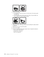
Page 113: ...password 12 Select Save Settings and press Enter Replacing the battery When replacing the battery you must replace it with a lithium battery of the same type from the same manufacturer To avoid possi...

Page 114: ...battery clip holds the battery securely 6 Replace the support bracket see Removing and installing the support bracket on page 38 7 Replace the cover and connect the cables 8 Turn on the computer 9 St...

Page 115: ...ce by following the troubleshooting procedures that IBM provides in the online help or in the publications that are provided with your system and software The information that comes with your system a...

Page 116: ...bout which products are supported by Support Line in your country or region go to http www ibm com services sl products For more information about Support Line and other IBM services go to http www ib...

Page 117: ...F ANY KIND EITHER EXPRESS OR IMPLIED INCLUDING BUT NOT LIMITED TO THE IMPLIED WARRANTIES OF NON INFRINGEMENT MERCHANTABILITY OR FITNESS FOR A PARTICULAR PURPOSE Some jurisdictions do not allow disclai...

Page 118: ...es other countries or both UNIX is a registered trademark of The Open Group in the United States and other countries Java and all Java based trademarks and logos are trademarks or registered trademark...

Page 119: ...recycling and disposal This unit contains materials such as circuit boards cables electromagnetic compatibility gaskets and connectors which may contain lead and copper beryllium alloys that require...

Page 120: ...eiver v Connect the equipment into an outlet on a circuit different from that to which the receiver is connected v Consult an IBM authorized dealer or service representative for help Properly shielded...

Page 121: ...se the power cord and plug with a properly grounded outlet IBM power cords used in the United States and Canada are listed by Underwriter s Laboratories UL and certified by the Canadian Standards Asso...

Page 122: ...pper Volta Uzbekistan Vanuatu Vietnam Wallis and Futuna Yugoslavia Federal Republic of Zaire 13F9997 Denmark 14F0015 Bangladesh Lesotho Maceo Maldives Namibia Nepal Pakistan Samoa South Africa Sri Lan...

Page 123: ...a Bolivia Caicos Islands Canada Cayman Islands Colombia Costa Rica Cuba Dominican Republic Ecuador El Salvador Guam Guatemala Haiti Honduras Jamaica Mexico Micronesia Federal States of Netherlands Ant...

Page 124: ...110 IntelliStation A Pro Type 6224 User s Guide...

Page 125: ...e eject button 9 CD ROM drive continued installing 44 CD ROM problems 87 channels SCSI 68 chart troubleshooting 86 components microprocessor board 36 of the computer 34 system board 35 computer config...

Page 126: ...lectrical input 3 enabling Broadcom NetXtreme Gigabit Ethernet Boot Agent 25 enabling continued the SCSI HostRAID feature 27 the Serial ATA RAID feature 26 environment 3 error LEDs 92 93 error message...

Page 127: ...microprocessor board 36 specifications 3 microprocessor board 36 connectors 36 error LEDs 93 installing 56 modes Ethernet 30 monitor problems 89 settings 15 mouse connector 66 problems 88 N notes impo...

Page 128: ...gram menu choices 30 SCSISelect Utility program continued starting 30 using 30 using to configure the SCSI controller 27 security anti intrusion 16 chassis intrusion detector 16 component protection 1...

Page 129: ...8 ports 68 Universal Serial Bus USB problems 92 updating system programs 17 using Adaptec RAID Configuration Utility 26 Configuration Setup Utility program 21 Enhanced Diagnostics diskette 95 IBM Conf...

Page 130: ...116 IntelliStation A Pro Type 6224 User s Guide...

Page 131: ......

Page 132: ...Part Number 24R8390 Printed in USA 1P P N 24R8390...

Reviews: