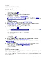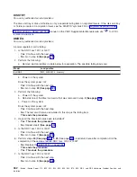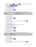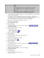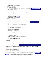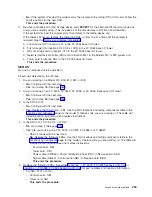
f.
The
Configuration
ID
displayed
is
defined
as
follows:
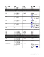
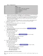
Table
1.
Configuration
ID
ID
Model
80
FC
5065,
FC
5066
81
FC
5074,
FC
5079
82
FC
9079
84
FC
5078,
FC
0578
90
FC
5075
91
Model
270
without
an
expansion
unit
and
without
a
removable
processor
92
Model
270
without
an
expansion
unit
and
with
a
removable
processor
93
Model
820
95
Model
270
with
an
expansion
unit
and
without
a
removable
processor
96
Model
270
with
an
expansion
unit
and
with
a
removable
processor
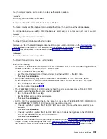
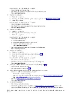
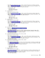
Is
the
correct
configuration
ID
displayed
for
the
tower
selected?
v
No
:
Continue
with
the
next
step.
v
Yes
:
Go
to
step
6
(See
page
5.
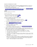
Perform
the
following
to
set
frame
Configuration
ID:
Note:
The
system
or
frame
that
will
display
the
ID
MUST
be
powered
down
with
ac
applied.
a.
Select
Function
07
on
the
system
control
panel
and
press
Enter
.
An
07**
will
display.
b.
Use
the
arrow
keys
to
increment
/
decrement
to
subfunction
A9
.
An
07A9
will
display.
c.
Press
Enter
.
An
07A9
00
will
displayed.
d.
Use
the
arrow
keys
to
increment
/
decrement
to
the
frame
address
of
the
box
you
want
to
set
the
Configuration
ID
(usually
02,
03,
...
for
the
towers,
01
for
system
unit
frames).
An
07nn
will
display
where
nn
is
the
frame
address.
e.
Press
Enter
.
An
07nn
00
will
display.
Note:
The
display
on
the
addressed
frame
should
now
be
blinking
on
and
off
(non-system
unit
frame
only).
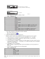
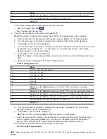
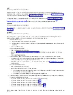
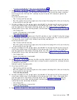
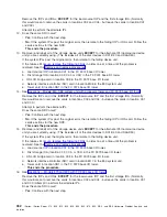
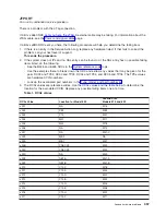
f.
Select
the
correct
Configuration
ID
from
the
following
table:
Table
2.
Configuration
ID
ID
Model
80
FC
5065,
FC
5066
81
FC
5074,
FC
5079
82
FC
9079
84
FC
5078,
FC
0578
342
iSeries:
iSeries
Server
270,
800,
810,
820,
825,
830,
840,
870,
890,
SB2,
and
SB3
Hardware
Problem
Analysis
and
Isolation


