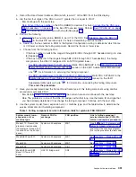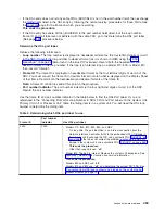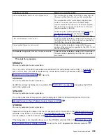
4.
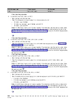
Record
the
Direct
Select
Address
(DSA)
which
is
word
7
of
the
SRC
from
the
SAL
display.
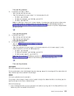
5.
Are
the
first
four
digits
of
the
DSA
in
word
7
greater
than
or
equal
to
0100?
v
No
:
Continue
with
the
next
step.
v
Yes
:
Convert
the
bus
number
in
the
DSA
(BBBB)
to
decimal.
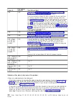
For
help
in
converting
the
DSA,
see
(in
the
Bus
PIP
overview
topic).
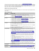
Perform
then
return
here
and
continue
with
step
8
(See
page
6.
Perform
the
following:
a.
Record
the
bus
number
value,
BBBB,
in
word
7
of
the
SRC.
See
(in
the
Bus
PIP
overview
topic)
for
help
in
determining
the
bus
number.
b.
Search
for
the
bus
number
in
HSM
or
the
System
Configuration
Listing
to
determine
which
frame
or
I/O
tower
contains
the
failing
component.
Record
the
frame
or
tower
type.
c.
Choose
from
the
following
options:
v
If
the
bus
number
is
not
in
the
range
4
through
23
(0004
through
0017
hexadecimal)
go
to
step
8
(See
page
v
If
the
bus
number
is
in
the
range
4
through
23
(0004
through
0017
hexadecimal),
the
failing
component
is
the
HSL
I/O
bridge
card
in
an
SPD
migrated
tower.
–
For
SPD
migrated
tower
FC
5077
go
to
symbolic
FRU
LBUSADP
in
the
manual
on
the
V5R1
Supplemental
Manuals
web
site
for
information
on
servicing
this
failing
component.
–
For
SPD
migrated
tower
FC
5033,
FC
5034,
FC
5035
go
to
symbolic
FRU
CVTCARD
in
the
manual
on
the
V5R1
Supplemental
Manuals
web
site
for
information
on
servicing
this
failing
component.
This
ends
the
procedure.
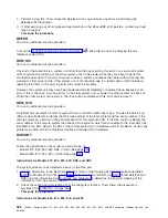
7.
Have
you
already
determined
the
frame
ID
and
frame
type
of
this
failing
component
using
another
procedure
or
symbolic
FRU?
v
No
:
Perform
then
return
here
and
continue
with
the
next
step.
v
Yes
:
The
problem
is
in
one
of
the
HSL
I/O
bridges
within
that
loop.
Use
the
frame
ID
and
type
that
you
have
already
determined
to
exchange
the
failing
component.
Continue
with
the
next
step.
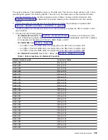
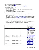
8.
Use
the
system
model,
tower,
expansion
unit,
or
machine
type,
and
the
table
below
to
determine
the
service
information
for
the
failing
component.
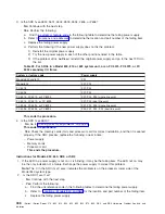
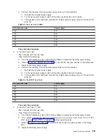
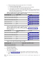
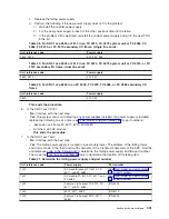
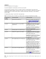
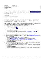
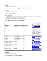
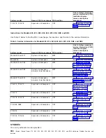
Table
1.
Failing
component
service
information
table
for
symbolic
FRU
SIIOADP
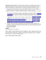
System
model,
tower,
expansion
unit,
or
machine
type
Name
of
FRU
to
exchange
FRU
position
Link
to
failing
component
service
information
(CCIN,
PN,
remove
and
replace
procedure)
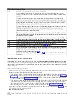
Model
270
-
Record
the
processor
feature
code
(characters
5
through
8
of
function
20
on
the
control
panel)
System
unit
backplane
MB1
Use
the
and
follow
the
Locations
diagram
link
for
the
processor
feature
code.
Models
800
and
810
System
unit
backplane
MB1
See
Model
820
System
unit
backplane
MB1
See
Model
825
System
unit
backplane
CB1
See
Models
830
and
SB2
Base
I/O
Tower
(FC
9074)
HSL
I/O
bridge
card
C08
See
Analyze
hardware
problems
451


