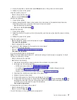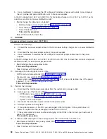
22.
Is
the
frame
that
will
not
power
on
part
of
a
shared
I/O
tower
loop?
v
Yes
:
Continue
with
the
next
step.
v
No
:
Go
to
step
24
(See
page
.
23.
The
failing
frame
can
only
be
powered
on
by
the
system
unit
that
is
connected
to
it
by
the
SPCN
frame-to-frame
cable.
Is
the
system
unit
powered
on?
v
No
:
Continue
with
the
next
step.
v
Yes
:
Go
to
step
25
(See
page
.
24.
Power
on
the
system
unit.
Does
the
failing
frame
power
on?
v
No
:
Continue
with
the
next
step.
v
Yes
:
This
ends
the
procedure.
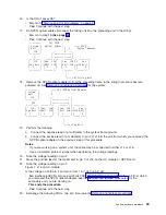
25.
Starting
from
J15
or
J16
on
the
system
unit,
go
to
the
first
frame
or
unit
in
the
frame
interconnect
cable
sequence
that
does
not
power
on.
Is
the
failing
unit
an
xSeries
(TM)
Server
Tower?
v
Yes
:
Go
to
step
27
(See
page
.
v
No
:
Continue
with
the
next
step.
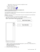
26.
Is
the
background
light
for
the
Data
display
on
the
control
panel
on,
is
the
power
on
LED
blinking,
or
are
there
any
characters
displayed
on
the
control
panel?
Note:
The
background
light
is
a
dim
yellow
light
in
the
Data
area
on
the
control
panel.
v
No
:
Go
to
step
29
(See
page
.
v
Yes
:
Go
to
step
44
(See
page
.
27.
Is
the
green
power
LED
on
the
xSeries
(TM)
Server
Tower
control
panel
blinking?
v
Yes
:
Continue
with
the
next
step.
v
No
:
Go
to
step
29
(See
page
.
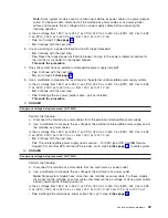
28.
Remove
the
top
cover
from
the
xSeries
(TM)
Server
Tower.
Is
the
two
digit
display
on
the
Integrated
xSeries
(TM)
Adapter
card
(CCIN
2689)
blinking
slowly?
v
Yes
:
Go
to
step
49
(See
page
.
v
No
:
Replace
the
following:
–
See
symbolic
FRU
–
See
symbolic
FRU
This
ends
the
procedure.
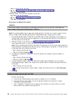
29.
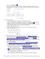
Use
a
multimeter
to
measure
the
ac
voltage
at
the
customer’s
ac
power
outlet.
DANGER
Dangerous
voltage
being
measured.
(RSFTD005)
Is
the
ac
voltage
from
200
V
ac
to
240
V
ac
or
from
100
V
ac
to
127
V
ac?
v
Yes
:
Continue
with
the
next
step.
v
No
:
Inform
the
customer
that
the
ac
voltage
at
the
power
outlet
is
not
correct.
This
ends
the
procedure.
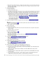
30.
Is
the
mainline
ac
power
cable
from
the
failing
unit
to
the
customer’s
ac
power
outlet
connected
and
seated
correctly
at
both
ends?
Note:
Some
systems
have
more
than
one
mainline
ac
power
cable.
For
these
systems,
check
both
power
cables
when
answering
the
following
questions.
v
Yes
:
Continue
with
the
next
step.
v
No
:
Connect
the
mainline
ac
power
cable
correctly
at
both
ends.
This
ends
the
procedure.
50
iSeries:
iSeries
Server
270,
800,
810,
820,
825,
830,
840,
870,
890,
SB2,
and
SB3
Hardware
Problem
Analysis
and
Isolation


