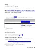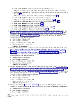
13.
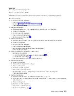
See
for
the
locations
and
remove
and
replace
procedures.
Replace
the
following
FRUs
in
order
one
at
a
time
until
the
problem
is
resolved.
Be
sure
to
IPL
in
SLOW
OVERRIDE
mode
after
each
replacement.
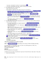
a.
Network
Interface
Controller
card
in
location
M06
in
the
830
system
unit.
b.
Clock
card
in
location
M06A
in
the
830
system
unit.
c.
Processor
regulator
card
in
location
M01
in
the
830
system
unit.
d.
Processor
card
in
location
M03
in
the
830
system
unit.
e.
Processor
card
in
location
M04
in
the
830
system
unit.
f.
System
unit
backplane
in
location
MB1
in
the
830
system
unit.
This
ends
the
procedure.
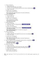
14.
This
is
a
Model
840,
SB3
system
unit
and
FC
9079
base
I/O
tower.
See
Replace
the
following
FRUs
in
order
one
at
a
time
until
the
problem
is
resolved.
See
the
Be
sure
to
IPL
in
SLOW
OVERRIDE
mode
after
each
replacement.
a.
Network
Interface
Controller
(NIC)
card
in
location
M17
in
the
840
system
unit.
b.
Clock
card
in
location
M19
in
the
840
system
unit.
c.
Processor
regulator
card
in
location
M04
in
the
840
system
unit.
d.
Processor
regulator
card
in
location
M07
in
the
840
system
unit.
e.
Processor
card
0
in
location
M05
in
the
840
system
unit.
f.
Processor
card
1
in
location
M18
in
the
840
system
unit.
g.
Processor
card
2
in
location
M06
in
the
840
system
unit.
h.
Processor
card
3
in
location
M16
in
the
840
system
unit.
i.
System
unit
backplane
in
location
MB1
in
the
840
system
unit.
This
ends
the
procedure.
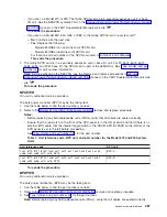
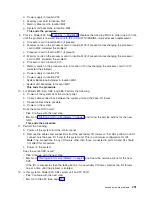
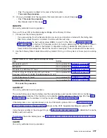
15.
This
is
a
Model
870
or
890
with
an
FC
9094
Base
I/O
Tower.
See
Replace
the
following
FRUs
in
order
one
at
a
time
until
the
problem
is
resolved.
Be
sure
to
IPL
in
SLOW
OVERRIDE
mode
after
each
replacement.
a.
HSL
I/O
bridge
card
in
position
C10
in
the
FC
9094
base
I/O
tower.
b.
Network
interface
controller
(NIC)
card
in
position
M41
in
the
Model
870
or
890
processor
tower.
c.
Replace
each
memory
card
one
at
a
time
in
the
Model
870
or
890
processor
tower.
d.
Replace
HSL
cable
C0
on
the
NIC
card
in
position
M41
in
the
Model
870
or
890
processor
tower.
This
ends
the
procedure.
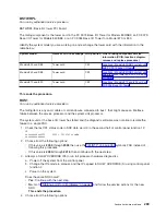
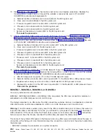
BUSCBL1,
BUSCBL2,
BUSCBL3,
or
BUSCBLx
For
use
by
authorized
service
providers.
BUSCBL1,
BUSCBL2,
BUSCBL3,
or
BUSCBLx:
HSL
Loop
cable,
the
HSL
loop
connections
(external
or
embedded)
or
an
HSL
interposer
card
in
an
HSL
loop.
The
failing
component
is
an
HSL
cable,
the
HSL
connections
(external,
internal,
or
embedded),
an
internal
HSL
ribbon
cable,
an
HSL
link
embedded
in
a
FRU,
or
an
HSL
interposer
card
in
an
HSL
loop.
Warning:
If
an
HSL
cable
is
pulled,
it
may
result
in
the
HSL
connection
being
lost
to
frames
that
were
in
a
loop
after
the
cable
is
reconnected.
To
fix
this,
you
will
need
to
cycle
power
on
the
frame
with
the
locked
HSL
connection.
If
this
occurs,
follow
the
Power
down,
power
on
instructions
(See
page
instructions
below
to
power
down
the
frames,
reconnect
the
HSL
cable,
and
power
the
frames
back
on.
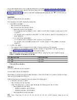
The
name
of
the
symbolic
FRU
given
in
the
Service
Action
Log
(SAL)
gives
information
about
the
type
of
connection
at
the
failing
port.
Use
information
about
the
connection
on
each
end
of
the
cable
to
determine
the
cable
type.
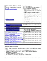
v
BUSCBL1
indicates
the
connection
is
an
optical
connection.
292
iSeries:
iSeries
Server
270,
800,
810,
820,
825,
830,
840,
870,
890,
SB2,
and
SB3
Hardware
Problem
Analysis
and
Isolation

