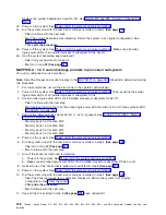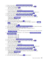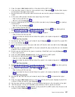
48.
Power
on
the
system.
See
49.
Did
the
system
stop
with
the
same
error
code
as
recorded
in
step
1
(See
page
?
v
Yes:
The
system
clock
card
just
reinserted
is
defective.
Replace
it.
Return
the
system
to
its
original
configuration.
See
This
ends
the
procedure.
v
No:
Continue
with
the
next
step.
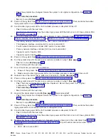
50.
Have
all
the
modules
listed
in
step
42
(See
page
been
reinstalled?
v
Yes:
The
symptom
has
changed.
Return
the
system
to
its
original
configuration.
See
This
ends
the
procedure.
v
No:
Go
to
step
45
(See
page
.
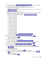
51.
Examine
the
amber
logic-power
LEDs
of
all
installed
processor
subsystem
DCAs.
52.
Are
all
amber
logic-power
LEDs
of
all
installed
processor
subsystem
DCAs
off?
v
Yes:
Continue
with
the
next
step.
v
No:
Replace
the
DCA
that
has
the
amber
logic
power
LED
that
did
not
turn
off.
See
symbolic
FRU
53.
Attention:
Before
replacing
the
system
backplane,
call
your
next
level
of
support.
Replace
the
system
backplane
at
location
M1.
54.
Power
on
the
system.
See
55.
Did
the
system
stop
with
the
same
error
code
as
recorded
in
step
1
(See
page
?
v
Yes:
Continue
with
the
next
step.
v
No:
The
system
backplane
was
defective.
Return
the
system
to
its
original
configuration.
See
This
ends
the
procedure.
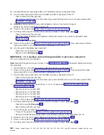
56.
Power
off
the
system.
See
Then,
make
sure
all
amber
logic-power
LEDs
of
all
installed
processor
subsystem
DCAs
are
off.
57.
Has
the
system
backplane
been
replaced?
v
Yes:
Call
your
next
level
of
support.
v
No:
Go
to
step
52
(See
page
.
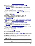
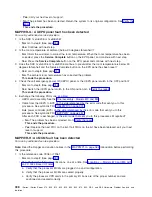
MAPPWR-E:
5.0
V
current/voltage
problem
in
processor
subsystem
For
use
by
authorized
service
providers.
Note:
Read
the
Danger
and
caution
notices
in
the
introduction
before
performing
this
procedure.
1.
For
future
reference,
record
the
error
code
and
the
location
codes
that
sent
you
to
this
procedure.
2.
Power
off
the
system.
See
Then,
examine
the
amber
logic-power
LEDs
of
all
installed
processor
subsystem
DCAs.
3.
Are
all
amber
logic-power
LEDs
of
all
installed
processor
subsystem
DCAs
off?
v
Yes:
Continue
with
the
next
step.
v
No:
Replace
the
DCA
that
has
the
amber
logic
power
LED
that
did
not
turn
off.
See
symbolic
FRU
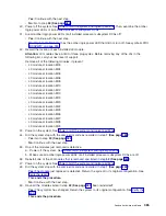
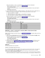
4.
Pull
out
the
following
books
about
25
mm
(1
inch),
if
present.
See
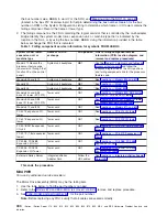
v
Memory
book
0
at
location
M18
v
Memory
book
1
at
location
M24
v
Memory
book
2
at
location
M07
v
Memory
book
3
at
location
M02
392
iSeries:
iSeries
Server
270,
800,
810,
820,
825,
830,
840,
870,
890,
SB2,
and
SB3
Hardware
Problem
Analysis
and
Isolation

