2.
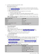
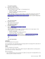
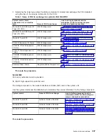
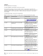
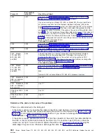
Determine
the
tower
type
where
the
failing
component
is
located
and
exchange
the
FRU
indicated
using
the
links
to
the
service
information
for
that
FRU.
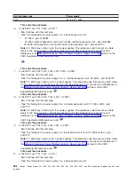
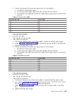
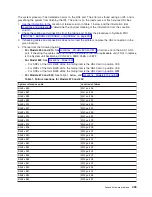
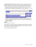
Table
1.
Name
of
FRU
to
exchange
for
symbolic
FRU
SIADPCD
System
model,
tower,
expansion
unit,
or
machine
type
Name
of
FRU
to
exchange
Link
to
failing
component
service
information
(CCIN,
Locations
diagram,
remove
and
replace
procedure)
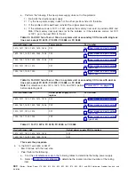
Models
830
and
SB2
Base
I/O
Tower
(FC
9074)
HSL
I/O
bridge
card
See
Models
840
and
SB3
Base
I/O
Tower
(FC
9079)
HSL
I/O
bridge
card
See
Models
870
and
890
HSL
I/O
bridge
card
See
FC
5074
Expansion
I/O
Tower
HSL
I/O
bridge
card
See
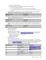
FC
5078,
FC
0578
Expansion
I/O
Unit
HSL
I/O
bridge
card
See
FC
5079
(1.8m
Expansion
I/O
Tower)
HSL
I/O
bridge
card
See
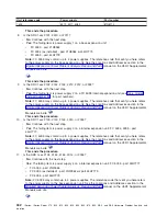
FC
5088,
FC
0588
Expansion
I/O
Unit
HSL
I/O
bridge
card
See
FC
5095,
FC
0595
Expansion
I/O
Tower
HSL
I/O
bridge
card
See
External
xSeries
Server
Integrated
xSeries
Adapter
Card
See
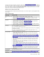
This
ends
the
procedure.
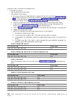
SI_CARD
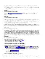
For
use
by
authorized
service
providers.
SI_CARD:
high-speed
link
controller
card.
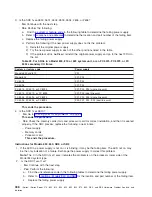
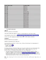
The
failing
component
is
the
network
interface
controller
(NIC)
card
in
the
system
unit.
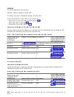
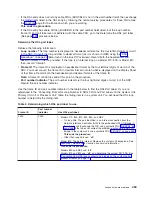
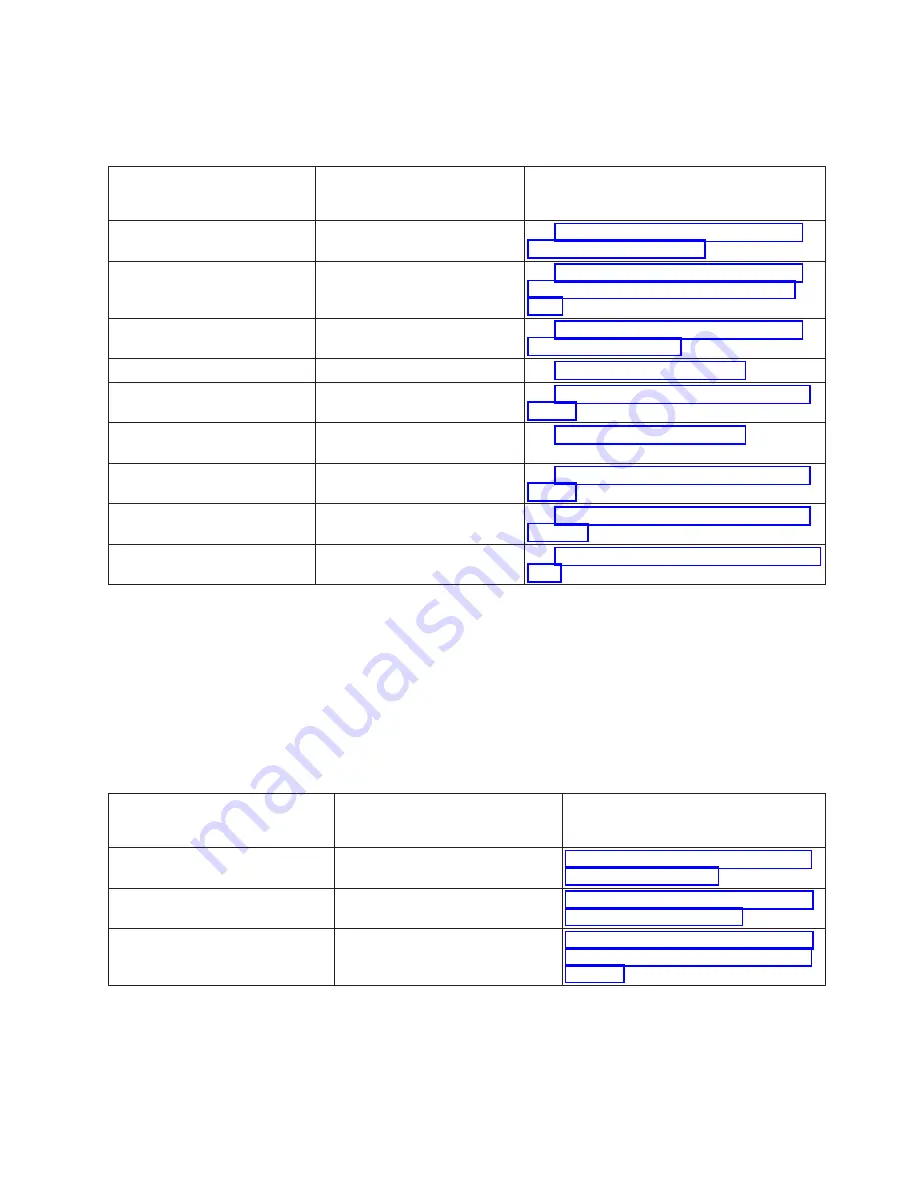
Use
the
system
model
and
the
table
below
to
determine
the
service
information
for
the
failing
component.
System
model
Name
of
FRU
to
exchange
Link
to
failing
component
service
information
(CCIN,
locations
diagram,
remove
and
replace
procedure)
Models
870
and
890
Network
Interface
Controller
Models
830
and
SB2
Network
Interface
Controller
Models
840
and
SB3
Network
Interface
Controller
This
ends
the
procedure.
Analyze
hardware
problems
447

