Follow
the
instructions
for
the
model
you
are
working
on:
v
Models
270
and
820
(See
page
v
Models
800,
810,
825,
830,
840,
870,
890,
SB2,
and
SB3
(See
page
Instructions
for
Models
270
and
820
1.
Choose
one
of
the
following:
v
If
you
are
working
on
a
Model
820,
use
Table
1.
below
to
determine
the
service
information.
This
ends
the
procedure.
v
If
you
are
working
on
a
Model
270,
continue
with
the
next
step.
2.
Is
function
20
available
on
the
system
unit
control
panel?
v
No
:
Continue
with
the
next
step.
v
Yes
:
Select
function
20
on
the
system
unit
control
panel.
Record
the
processor
feature
code
(characters
5
through
8).
Use
Table
1.
below
to
determine
the
service
information.
This
ends
the
procedure.
3.
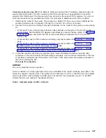
The
system
unit
backplane
is
in
position
MB1.
To
determine
which
system
unit
backplane
is
installed,
remove
the
cover
on
the
left
side.
See
Then,
continue
with
the
next
step.
4.
Examine
the
card
positions
on
the
system
unit
backplane.
v
If
there
are
card
positions
labeled
M01
and
M02,
then
you
are
working
on
a
Model
270
with
a
Network
Interface
Controller
(NIC)
embedded
in
the
processor
card.
v
If
there
are
no
card
positions
labeled
M01
and
M02,
then
you
are
working
on
a
Model
270
with
a
Network
Interface
Controller
(NIC)
embedded
in
the
system
unit
backplane.
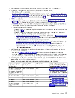
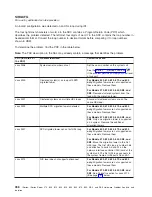
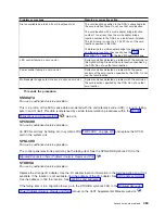
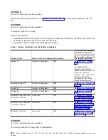
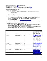
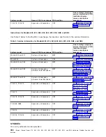
Table
1.
Service
information
for
Models
270
and
820
System
model
Name
of
FRU
to
exchange
FRU
position
Link
to
failing
component
service
information
(CCIN,
locations
diagram,
remove
and
replace
procedure)
Model
270
System
unit
backplane
MB1
Go
to
and
follow
links
for
either
the
processor
feature
code
or
what
FRU
the
NIC
is
embedded
in.
(The
processor
feature
code
is
characters
5
through
8
of
function
20
on
the
control
panel.)
Model
820
System
unit
backplane
MB1
See
FC
5065,
FC
5066
Expansion
unit
backplane
CB1
See
Note:
Position
CB1
is
the
same
on
the
FC
5074,
FC
5065,
and
FC
5066.
FC
5074,
FC
5079
Expansion
unit
backplane
CB1
See
or
FC
5075
Expansion
unit
backplane
CB1
See
Analyze
hardware
problems
465

