The
communication
between
the
workstation
controller
and
a
workstation
was
interrupted
during
an
active
session.
Possible
causes
include:
v
The
power
for
the
workstation
was
turned
off,
then
on.
v
A
temporary
loss
of
power
to
the
workstation
occurred.
VPDCONC
For
use
by
authorized
service
providers.
The
failing
component
is
the
VPD
concentrator
hardware.
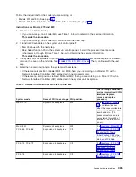
1.
Choose
from
the
following
options:
v
If
you
are
on
a
Model
270,
800,
810,
or
820:
Replace
the
system
unit
backplane
at
location
MB1.
See
for
the
model
you
are
working
on
to
find
part
information
and
links
to
the
remove
and
replace
procedures.
This
ends
the
procedure.
v
If
you
are
on
a
Model
825,
830,
840,
870,
890,
SB2,
or
SB3:
Continue
with
the
next
step.
2.
Is
this
system
a
Model
825?
v
No:
Continue
with
the
next
step.
v
Yes:
Replace
the
system
unit
backplane
at
location
CB1.
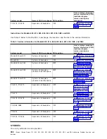
See
3.
Is
this
system
a
Model
830
with
SB2
system
unit
and
FC
9074?
v
No
:
Continue
with
the
next
step.
v
Yes
:
Replace
the
following
FRUs
in
order
one
at
a
time
until
the
problem
is
resolved.
Be
sure
to
IPL
in
SLOW
OVERRIDE
mode
after
each
replacement.
See
for
part
number
and
remove
and
replace
information.
a.
Clock
card
in
location
M06A
in
the
830
system
unit.
b.
Network
interface
controller
(NIC)
card
in
location
M06
in
the
830
system
unit.
This
ends
the
procedure.
4.
Is
this
a
Model
840,
SB3
system
unit
and
FC
9079
base
I/O
tower?
v
No
:
Continue
with
the
next
step.
v
Yes
:
Replace
the
clock
card
in
location
M19
in
the
840
system
unit.
Be
sure
to
IPL
in
SLOW
OVERRIDE
mode
after
each
replacement.
See
for
part
number
and
remove
and
replace
information.
This
ends
the
procedure.
5.
This
is
a
Model
870
or
890
system
unit
with
FC
9094
base
I/O
tower.
Replace
the
Network
interface
controller
(NIC)
card
in
position
M41
in
the
870
or
890
processor
tower.
See
This
ends
the
procedure.
VPDPART
For
use
by
authorized
service
providers.
A
VPDPART
may
be
failing.
Attention:
AC
power
must
be
removed
from
the
system
before
removing
or
installing
regulator
3.
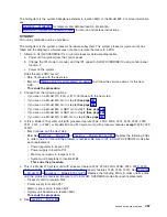
Perform
the
following
to
determine
the
part
for
the
failing
VPDPART.
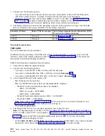
The
address
of
the
failing
frame
and
unit
is
shown
in
the
second,
third,
and
fourth
characters
of
the
4
leftmost
characters
of
the
SRC.
11-x
xFFU-xxxx
(F=frame
and
U=unit).
Follow
the
instructions
for
the
model
you
are
working
on:
Analyze
hardware
problems
479

