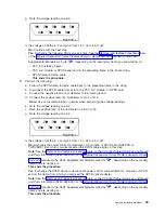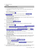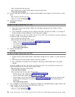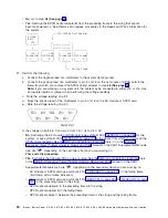
v
No
:
This
ends
the
procedure.
18.
Do
SPCN
optical
cables
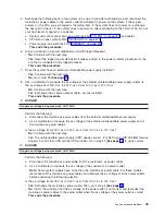
A
connect
the
failing
frame
B
to
the
preceding
frame
in
the
string?
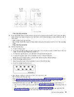
.---------.
(A)
SPCN
|
System
|
Optical
Cables
-.
.-----
SPCN
|
Unit
|
|
V
Optical
|
J15
|
.-.
V
.-.
Adapter
’----.----’
|
+------------+
|
|
|
+------------+
|
.----’----.
.-------’-+
.-------’-+
.---------.
|
J15
|
|
J16|
|
J15|
|
|
|Frame
J16+-+J15
Frame|
|Frame
J16+-+J15
Frame|
|
1
|
|
2
|
|
3
|
|
4
|
’---------’
’---------’
’---------’
’---------’
^
’----
(B)
Failing
Frame
v
No
:
Go
to
step
20
(See
page
.
v
Yes
:
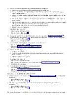
Remove
the
SPCN
optical
adapter
A
from
the
preceding
frame
in
the
string
that
cannot
become
powered
on.
Note:
See
the
topic,
or
the
FC
504x
Problem
Analysis
and
Repair
and
Parts
information
(SY44-4934-00),
or
the
manual
on
the
V5R1
Supplemental
Manuals
web
site
,
depending
on
the
secondary
frame
you
are
working
on.
.---------.
.---
(A)
SPCN
optical
adapter
|
System
|
|
|
Unit
|
V
|
J15
|
.-.
.-.
’----.----’
|
+------------+
|
|
|
+------------+
|
.----’----.
.-------’-+
.-------’-+
.---------.
|
J15
|
|
J16|
|
J15|
|
|
|Frame
J16+-+J15
Frame|
|Frame
J16+-+J15
Frame|
|
1
|
|
2
|
|
3
|
|
4
|
’---------’
’---------’
’---------’
’---------’
^
|
’---
Failing
frame
Continue
with
the
next
step.
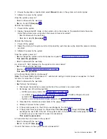
19.
Perform
the
following:
a.
Connect
the
negative
lead
of
a
multimeter
to
the
system
frame
ground.
b.
Connect
the
positive
lead
of
a
multimeter
to
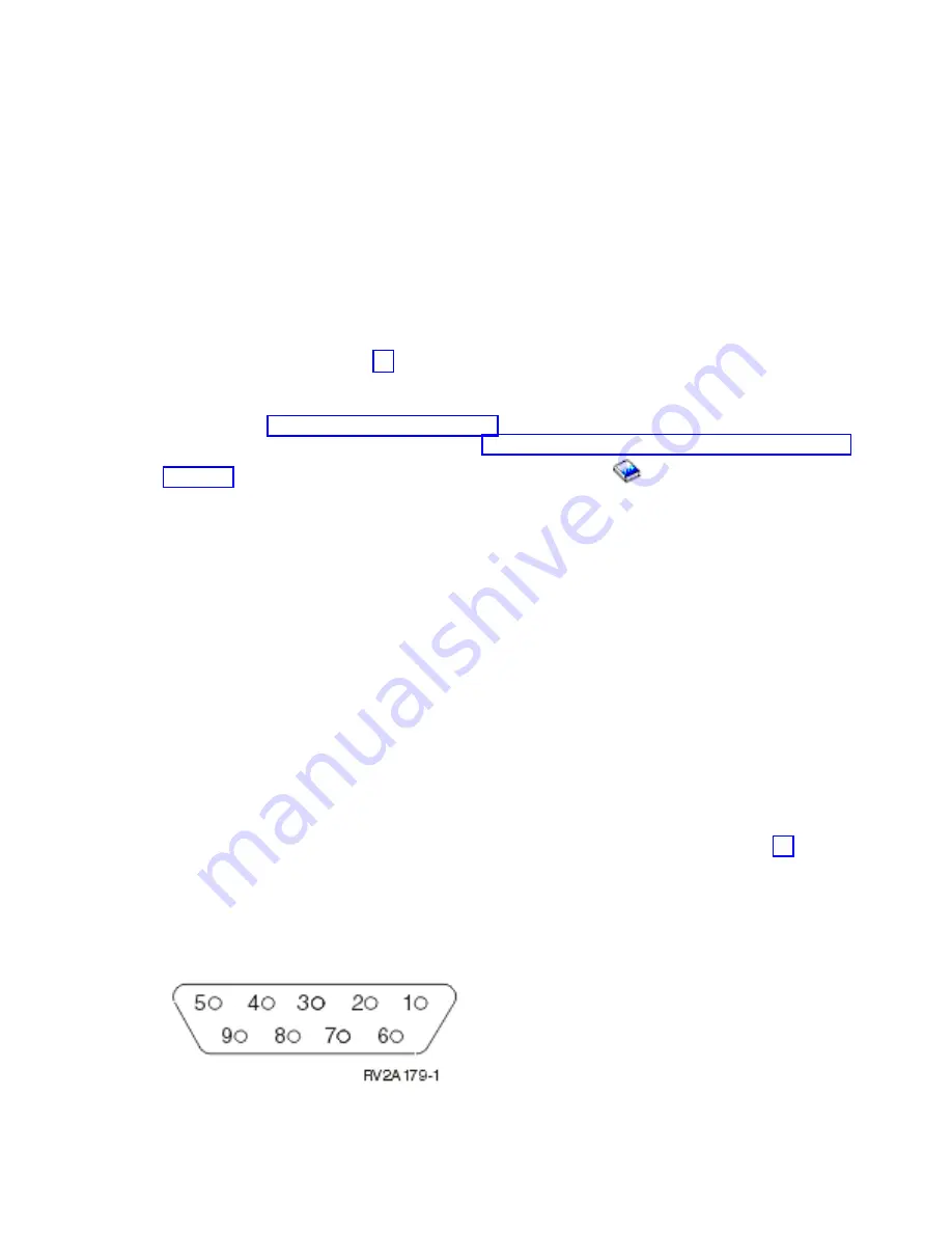
pin
2
of
J16
on
the
PCC,
AC
module,
or
SPCN
card
in
the
frame
from
which
you
removed
the
SPCN
optical
adapter
in
step
18
(See
page
.
Note:
If
you
are
working
on
a
system
unit,
the
cable
may
be
connected
to
either
J15
or
J16.
Use
an
insulated
probe
or
jumper
when
performing
the
voltage
readings.
c.
Note
the
voltage
reading
on
pin
2.
d.
Move
the
positive
lead
of
the
multimeter
to
pin
3
of
J16
on
the
PCC.
e.
Note
the
voltage
reading
on
pin
3.
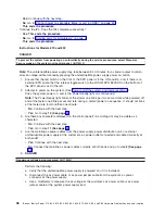
Is
the
voltage
on
both
pin
2
and
pin
3
from
1.5
V
dc
to
5.5
V
dc?
Analyze
hardware
problems
47

