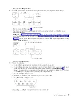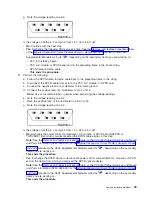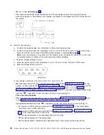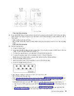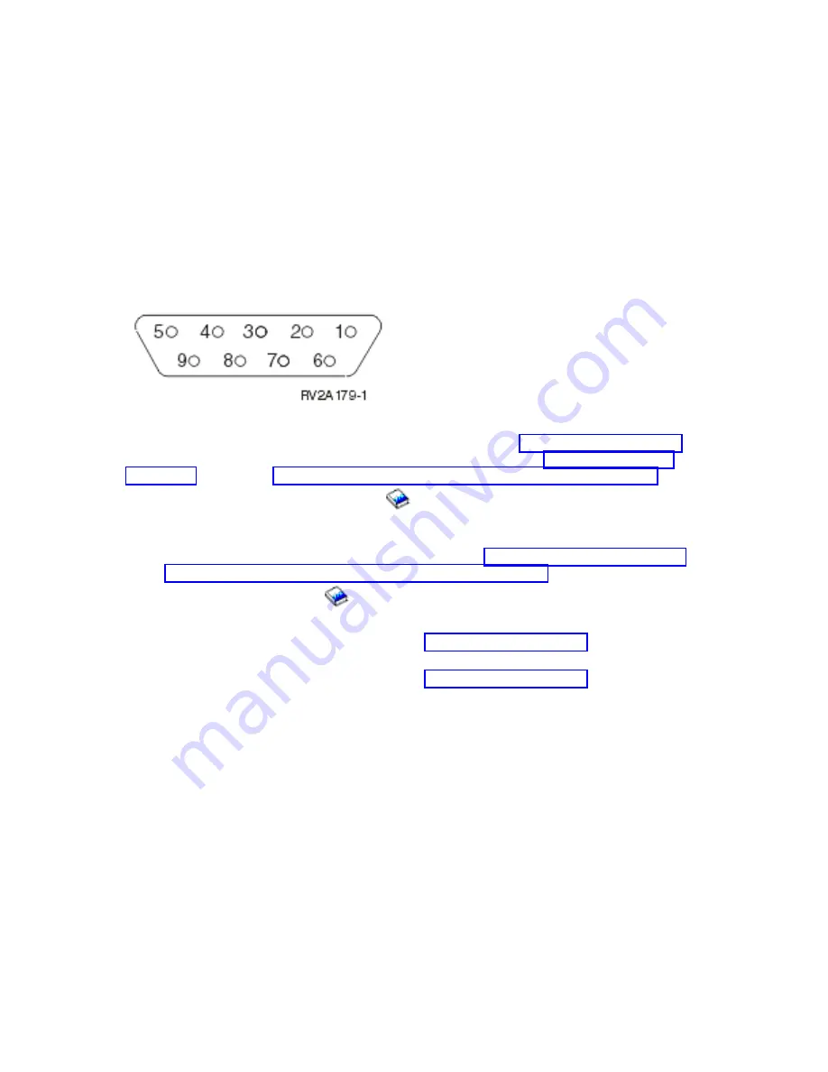
–
SPCN
frame-to-frame
cable.
This
ends
the
procedure.
50.
Perform
the
following:
a.
Follow
the
SPCN
frame-to-frame
cable
back
to
the
preceding
frame
in
the
string.
b.
Disconnect
the
SPCN
cable
from
J16
on
the
AC
module
or
SPCN
card.
c.
Connect
the
negative
lead
of
a
multimeter
to
the
system
frame
ground.
d.
Connect
the
positive
lead
of
a
multimeter
to
pin
2
of
J16
on
the
AC
module
or
SPCN
card.
Note:
Use
an
insulated
probe
or
jumper
when
performing
the
voltage
readings.
e.
Note
the
voltage
reading
on
pin
2.
f.
Move
the
positive
lead
of
the
multimeter
to
pin
3
of
J16
on
the
AC
module
or
SPCN
card.
g.
Note
the
voltage
reading
on
pin
3.
Is
the
voltage
on
both
pin
2
and
pin
3
from
1.5
V
dc
to
5.5
V
dc?
v
No
:
Exchange
the
AC
module
or
SPCN
card
(see
symbolic
FRU
from
which
you
disconnected
the
SPCN
cable
earlier
in
this
step.
See
the
topic,
or
the
manual
on
the
V5R1
Supplemental
Manuals
web
site
,
depending
on
the
secondary
frame
or
unit
you
are
working
on.
This
ends
the
procedure.
v
Yes
:
Exchange
the
following
FRUs,
one
at
a
time.
See
the
topic,
or
the
manual
on
the
V5R1
Supplemental
Manuals
web
site
,
depending
on
the
secondary
frame
you
are
working
on.
–
SPCN
frame-to-frame
cable
–
AC
module
or
SPCN
card
(see
symbolic
FRU
in
the
failing
frame
or
unit
–
AC
module
or
SPCN
card
(see
symbolic
FRU
in
the
preceding
frame
of
the
frame
string
This
ends
the
procedure.
Instructions
for
Models
800,
810,
825,
870,
and
890
1.
Is
the
unit
that
does
not
power
on
a
shared
unit
that
is
switched
to
the
system
unit
that
does
not
have
a
frame
to
frame
cable
attached
to
it?
v
No
:
Continue
with
the
next
step.
v
Yes
:
The
secondary
unit
that
is
switched
to
the
system
unit
that
does
not
have
a
frame-to-frame
cable
attached
to
it
MUST
be
switched
to
the
system
unit
with
a
frame-to-frame
cable
attached
to
it
to
service
it.
Do
this
and
continue
with
the
next
step.
2.
Power
on
the
system.
3.
Starting
from
J15
or
J16
on
the
system
unit,
go
to
the
first
unit
in
the
unit
interconnect
cable
sequence
that
does
not
power
on.
4.
Is
the
background
light
for
the
Data
display
on
the
control
panel
on,
the
power
on
LED
blinking,
or
are
there
any
characters
displayed
on
the
control
panel?
Note
:
The
background
light
is
a
dim
(yellow)
light
in
the
Data
area
on
the
control
panel.
56
iSeries:
iSeries
Server
270,
800,
810,
820,
825,
830,
840,
870,
890,
SB2,
and
SB3
Hardware
Problem
Analysis
and
Isolation


