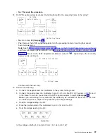
v
No
:
Continue
with
the
next
step.
26.
Perform
the
following:
a.
Follow
the
SPCN
frame-to-frame
cable
back
to
the
preceding
unit
in
the
string.
b.
Disconnect
the
SPCN
cable
from
J16
connector.
c.
Connect
the
negative
lead
of
a
multimeter
to
the
system
frame
ground.
d.
Connect
the
positive
lead
of
a
multimeter
to
pin
2
of
J16
connector.
Note
:
Use
an
insulated
probe
or
jumper
when
performing
the
voltage
readings.
e.
Note
the
voltage
reading
on
pin
2.
f.
Move
the
positive
lead
of
the
multimeter
to
pin
3
of
J16
connector.
g.
Note
the
voltage
reading
on
pin
3.
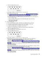
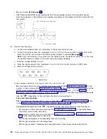
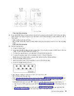
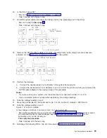
Figure
9.
J16
connector
(RV2A179-1)
Is
the
voltage
on
both
pin
2
and
pin
3
from
1.5
V
dc
to
5.5
V
dc?
v
Yes
:
Exchange
the
following
FRUs,
one
at
a
time
(see
the
–
SPCN
frame-to-frame
cable
–
SPCN
card
(see
symbolic
FRU
in
the
failing
unit
–
SPCN
card
(see
symbolic
FRU
in
the
preceding
unit
of
the
unit
string
This
ends
the
procedure.
v
No
:
Exchange
the
SPCN
card
(see
symbolic
FRU
from
the
unit
which
you
disconnected
the
SPCN
cable
in
the
previous
step
of
this
procedure.
See
the
This
ends
the
procedure.
Problem
isolation
For
use
by
authorized
service
providers.
This
topic
will
help
you
identify
and
isolate
the
problem
the
system
is
experiencing.
You
will
then
be
directed
how
to
resolve
the
issue.
Symbolic
field
replaceable
units
(FRUs),
faling
items
(FIs),
and
Bus
problem
isolation
procedures
(PIPs)
will
use
the
terms
″
partition
″
and
″
logical
partition
″
to
indicate
any
single
partition
in
a
system
which
has
multiple
partitions.
If
the
system
you
are
working
on
does
not
have
multiple
partitions,
then
the
terms
refer
to
the
primary
partition.
The
following
sub-topics
are
included:
v
v
v
Problem
isolation
procedures
(PIPs)
For
use
by
authorized
service
providers.
Bus,
high-speed
link
(HSL)
PIPs
Communications
PIPs
Disk
unit
PIP
Intermittent
PIPs
Analyze
hardware
problems
61

