


Removing and replacing FRUs
FRUs must be installed only by trained service technicians.
The illustrations in this document might differ slightly from your hardware.
Microprocessor
Read the following important guidelines before removing a microprocessor that is
not faulty (for example, when replacing the system board assembly).
Attention:
Do
not
use a thermal grease syringe with this FRU.
If you are not replacing a defective heat sink or microprocessor, the grease on the
heat sink and microprocessor will remain effective if you perform the following
steps:
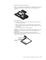
1. Carefully handle the heat sink and microprocessor when removing or installing
these components. Do not touch the grease or otherwise allow it to become
contaminated.
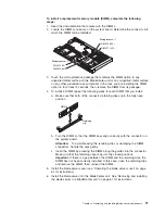
2. For dual-microprocessor systems, since the microprocessor and the heat sink
are a matched set, first transfer the heat sink and microprocessor from one
socket to the new system board; then, transfer the other heat sink and
microprocessor. (This will ensure that the grease remains evenly distributed
between each heat sink and microprocessor.)
The following sections contain the instructions for removing and replacing a
microprocessor.
Notes:
v
The heat sink FRU is packaged with the thermal grease applied to the underside.
This thermal grease is not available as a separate FRU. The heat sink must be
replaced when new grease is required, such as when a defective microprocessor
is replaced or if the grease is contaminated.
v
If you need to install a new heat sink for any reason, first remove the thermal
grease from the microprocessor with an alcohol pad before attaching the new
heat sink.
v
The microprocessor FRU for this system board includes a heat sink.
v
A heat sink FRU can be ordered separately if the grease becomes contaminated.
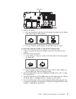
To remove a microprocessor, complete the following steps:
1. Read the safety information that begins on page v, the “Installation guidelines”
on page 59 and “Handling static-sensitive devices” on page 60.
2. Shut down the operating system, turn off the blade server, and remove the
blade server from the BladeCenter unit (see “Removing and installing the blade
server in a BladeCenter unit” on page 61).
3. Carefully lay the blade server on a flat, non-conductive surface.
4. Open the blade server cover (see “Operating the blade server cover” on page
64 for instructions).
5. Remove the bezel assembly (see “Removing and replacing the bezel assembly”
on page 66 for instructions).
78
AMD Opteron LS20 Type 8850 for IBM BladeCenter: Problem Determination and Service Guide
Summary of Contents for LS20 - BladeCenter - 8850
Page 1: ...AMD Opteron LS20 Type 8850 for IBM BladeCenter Problem Determination and Service Guide...
Page 2: ......
Page 3: ...AMD Opteron LS20 Type 8850 for IBM BladeCenter Problem Determination and Service Guide...
Page 14: ...xii AMD Opteron LS20 Type 8850 for IBM BladeCenter Problem Determination and Service Guide...
Page 72: ...58 AMD Opteron LS20 Type 8850 for IBM BladeCenter Problem Determination and Service Guide...
Page 104: ...90 AMD Opteron LS20 Type 8850 for IBM BladeCenter Problem Determination and Service Guide...
Page 114: ...100 AMD Opteron LS20 Type 8850 for IBM BladeCenter Problem Determination and Service Guide...
Page 115: ......
Page 116: ...Part Number 49Y0167 Printed in USA 1P P N 49Y0167...